


LC1 as Narrowband issue

Thread Starter
TECH Apprentice
Joined: Jun 2008
Posts: 391
Likes: 0
From: Mesa, AZ
Well, the audiohelix wiring site that is referenced by everything I have searched for is down. SO... here goes...
I'm using an LC1 as a narrowband and a wideband. Hooked up all the grounds to a single point, except the blue, which is always grounded to the chassis. The multiple ground point (white wire and black wire) then connects to a 3-way switch and grounds either through the ground on the HPTuners interface (which grounds through the OBD2 port), or to a chassis ground when I'm not logging.
Yellow wire (Set up as narrowband replacement, timing set to 1/6 sec, 0-1V for the stock LC1 voltage/AFRs on the narrowband side) running down to Pin B in the stock NBO2 sensor plug (cut the connector off my old narrowband and attached to it)
Brown wire connects to my HPTuners EIO block, and has the signal wire for an AFR gage tapped into it at this point.
Red wire running to Pin D in the stock NBO2 sensor plug to get +12V.
Now, this setup worked great for about 2 weeks while I was slowly figuring out the tune for my car, but now the ECU will only read ~.447v to .451v from the narrowband output, I also get this same readout when I disconnect the signal wire from the LC1 unit. Using a multimeter, the voltage difference between the narrowband output and a chassis ground seems to output correctly (varying between .11v and 1.1v).
I rewired and put in the stock O2 sensor, and it reads very close to the sensor on the other bank, switching normally, ~.1v to .8v.
I just finished replacing the LC1 controller with a replacement unit (Amazon's return policy is quite nice for stuff like this), but it's doing exactly the same thing!
Any ideas would be helpful.
//edit//
So... guess what? I'm a doofus, as per the usual.
Headers melted through the sheathing on some wires on the bundle included with the o2 sensor bundle. If I shake them JUST right, then the o2 sensors all work great. Otherwise... the ECU reads some godawful voltages from other wires, or disconnects it.
Good news... this also explains my speed sensor issues.
Last edited by AxisOfOil; Aug 17, 2011 at 10:48 PM. Reason: ...hehe
The white wire should go to the NBO2 "low signal" pin A
Don't connect the system ground white wire to your device's analog ground point.
This wire emits 0.1 volts and will skew the analog signal.
12v power and ground can be had through the NBO2 plug as well
Red = pin D
Blue = pin C
Yellow or Brown = pin B
White = pin A
NBO2 simulation seems to be hit or miss from what I've read.
I personally suggest using the stock NBO2s for LTFT/STFT.
Thread Starter
TECH Apprentice
Joined: Jun 2008
Posts: 391
Likes: 0
From: Mesa, AZ
First and foremost, I'm not attacking what you're saying, I welcome your help and would appreciate continued help.
I'm not sure what you mean by connecting the white wire to my device's analog ground point, but I can only assume that you mean the point at which the HPTuners module is grounding. But, Innovate specifically recommends them to be grounded to the same location. I also can't detect a ground offset between my chassis ground, the ground location on my EIO module (plugs into the side of the HPTuners device thingy and connects to the ECU ground), or the battery's negative terminal, so I don't think mine is offsetting by 0.1V...
I also checked my readings via HPTuners against the serial connection to the LC1 simultaneously, and they have the same readings to within .1AFR from 12-16 AFR (I wasn't able to check them past this), so I didn't even have to correct for any ground offset there. I'm just quite confused... hopefully repairing/re-insulating/looming+aluminum-taping the damaged wires fixes all my issues!
Also, I did try using the stock NBO2's for LTFT/STFT tuning... didn't work out so terribly well for me... if you would like to help on that end, step inside this thread:
https://ls1tech.com/forums/pcm-diagn...ng-issues.html
The white wire should go to the NBO2 "low signal" pin A
Don't connect the system ground white wire to your device's analog ground point.
This wire emits 0.1 volts and will skew the analog signal.
12v power and ground can be had through the NBO2 plug as well
Red = pin D
Blue = pin C
Yellow or Brown = pin B
White = pin A
NBO2 simulation seems to be hit or miss from what I've read.
I personally suggest using the stock NBO2s for LTFT/STFT.
Don't connect the system ground white wire to your device's analog ground point.
This wire emits 0.1 volts and will skew the analog signal.
12v power and ground can be had through the NBO2 plug as well
Red = pin D
Blue = pin C
Yellow or Brown = pin B
White = pin A
NBO2 simulation seems to be hit or miss from what I've read.
I personally suggest using the stock NBO2s for LTFT/STFT.
The white wire can't come in direct contact with the analog ground and
it should be feeding the 0.1 volt to the low signal pin of the PCM like the stock NBO2 does.
Innovate's instructions suck, that's why so many people have "issues" with the LC-1.
Slope, intercept (transfer function), can be improper too.
IMO do not split a signal between a gauge and another device.
Innovate's way:
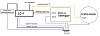
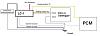
The right way:
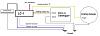
To PCM:
Are LTFTs/STFTs radically different between bank1 & bank2?
it should be feeding the 0.1 volt to the low signal pin of the PCM like the stock NBO2 does.
Innovate's instructions suck, that's why so many people have "issues" with the LC-1.
Slope, intercept (transfer function), can be improper too.
IMO do not split a signal between a gauge and another device.
Innovate's way:

The right way:

To PCM:

Are LTFTs/STFTs radically different between bank1 & bank2?
When the PCM data stays pinned to ~450mV but
the input signal is switching, that's a usual fault
response. Check codes and/or how you may have
"killed" them (no SES != no error).
One problem with wideband-as-narrowband is that
it introduces a significant lag, with whatever internal
sampling, filtering, averaging goes on. This delay can
destabilize the loop. If you have access to these
internal settings, make them as close as you can to
a real time, raw response.
Thread Starter
TECH Apprentice
Joined: Jun 2008
Posts: 391
Likes: 0
From: Mesa, AZ
When the PCM data stays pinned to ~450mV but
the input signal is switching, that's a usual fault
response. Check codes and/or how you may have
"killed" them (no SES != no error).
One problem with wideband-as-narrowband is that
it introduces a significant lag, with whatever internal
sampling, filtering, averaging goes on. This delay can
destabilize the loop. If you have access to these
internal settings, make them as close as you can to
a real time, raw response.
the input signal is switching, that's a usual fault
response. Check codes and/or how you may have
"killed" them (no SES != no error).
One problem with wideband-as-narrowband is that
it introduces a significant lag, with whatever internal
sampling, filtering, averaging goes on. This delay can
destabilize the loop. If you have access to these
internal settings, make them as close as you can to
a real time, raw response.
I just checked all the wiring... the loom was a bit melted, but the wires are solid and have good connectivity all the way to the PCM pins from the sensors.
I will set the wideband back to instant, although it's been recommended by a few LS1tech threads that it should be set to 1/6 sec averaging to best emulate the stock sensor.
The stock sensor is now ALSO setting to ~450.
By the way, I have been "killing" codes by unchecking the "ses enable" box, and setting the Error Mode to 3 - No Error Reported. Is this the correct way?
Trending Topics
LS1 Tech Stories
The Best V8 Stories One Small Block at Time

Gas Monkey Built a 6-Wheel Ferrari Testarossa With a Corvette LT4 Engine
Verdad Gallardo
7 Most Reliable High-Performance Engines GM Has Ever Built
Verdad Gallardo
Amazing '71 Camaro Restomod Is Modern Muscle Car Under the Skin
Verdad Gallardo
6 Common C5 Corvette Failures and What's Involved In Repairing Them
Pouria Savadkouei
Retro Modern Bandit Pontiac Trans AM Comes With Burt Reynolds' Autograph
Verdad Gallardo
Top 10 Greatest Cadillac V Series Performance Models Ever, Ranked
Pouria Savadkouei
Top 10 Most Powerful Chevy Trucks Ever Made!

Hennessey's New Supercharged Silverado ZR2 Has 700 HP
Verdad Gallardo
Coachbuilt N2A Anteros Is an LS2-Powered C6 Corvette In Italian Clothes
Verdad Gallardo Thread Starter
TECH Apprentice
Joined: Jun 2008
Posts: 391
Likes: 0
From: Mesa, AZ
I will wipe them all and give it a shot. Have an update in about 5 mins. I can't find anything open in the harness.


Thread Starter
TECH Apprentice
Joined: Jun 2008
Posts: 391
Likes: 0
From: Mesa, AZ
wiped them all... no dice. So... instead of trying to find a break somewhere in the harness, could I just wire the High signal wire straight to the lead from the blue, pin 66 connector (purple wire)?
Thread Starter
TECH Apprentice
Joined: Jun 2008
Posts: 391
Likes: 0
From: Mesa, AZ
Also, I hooked the white wire to the nbo2 low signal, and the yellow wire to the nbo2 high signal, both at the PCM now instead of the o2 plug. still pulling switched +12 from the O2 plug, and using chassis ground for the heater wire. It's working again! Looks like there was a break somewhere in the harness.
Thread Starter
TECH Apprentice
Joined: Jun 2008
Posts: 391
Likes: 0
From: Mesa, AZ
Yep, I did that, that's what I was saying. It doesn't seem to change how it works, but in theory, it should be more accurate that way. (And my PCM just won't read from pin B... silly broken wires).