
On the Road to Removing the Shock Towers
 03-25-2011, 06:15 AM
#1

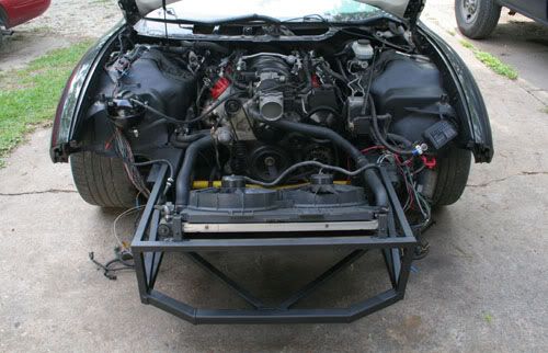
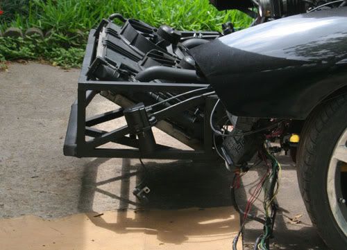
As I get closer to building my new front suspension I wanted to take a serious look at removing the shock towers and how best to retain strength and some measure of crash worthiness (even though that is not the priority).
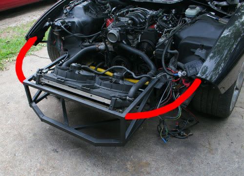
So far the sheet metal in front of the wheels is gone and a new tubular structure has been built.
So far the sheet metal in front of the wheels is gone and a new tubular structure has been built.
 03-25-2011, 06:17 AM
#2
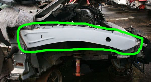
I think it would be best to keep the structure under the fenders as it is load bearing (to a certain extent) and serves as the plastic fender mount. This piece:
So I will have the 2 main lower rails (which will be reinforced) and the 2 fender supports:
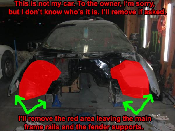
So I will have the 2 main lower rails (which will be reinforced) and the 2 fender supports:
Last edited by JasonWW; 03-25-2011 at 06:58 AM.
 03-26-2011, 07:01 AM
#4

I'm not a structural engineer, by any means, but I messed around with oval track cars for a while in the 80s, and I can assure you they depend on structural integrity. I would say that the inner fenders, being a load bearing, formed sheet metal shape, add a fair amount of stiffness to the front end of the unit body, and removing them will weaken the front end, unless something takes their place.
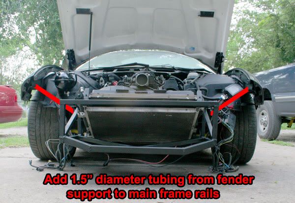
Having said that, I would think that if you welded in a "fish plate" of 1/8" steel to the upper edge of the firewall, and then welded in a 1.75" diameter, DOM steel tubing diagonal, between the firewall and the forward end of the frame rail, where you've added your radiator support, you'd probably retain the strength of the front end. Look at some of the NASCAR frames.
Go to this link, and look at the lead picture of the oval track frame, you'll see what I mean...
www.nerace.com/
03-26-2011, 11:07 AM
#5
I think I know what you mean. The weight of the engine is going to bend the frame rails between the K-member and the firewall. A straight tube from the top rear of the firewall to in front of the K-member would definitely be an efficient way to strengthen the frame. A tube could physically fit if placed just to the right of the AC box and just to the left of the brake booster. The issue I have is that to weld on the top of the firewall would require pulling the engine and more importantly the dash and everything behind it. That would really suck.
Another option and what I was considering is to add a side plate to the frame rail like so:
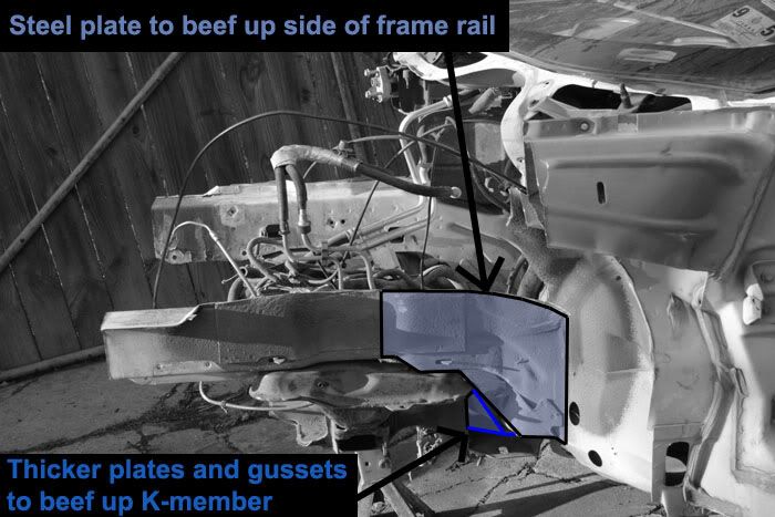
Holes can be added to reduce weight and to add contact area. Plate can be added to the inner frame rails also if need be.
Another option and what I was considering is to add a side plate to the frame rail like so:
Holes can be added to reduce weight and to add contact area. Plate can be added to the inner frame rails also if need be.
Last edited by JasonWW; 03-26-2011 at 11:37 AM.
03-27-2011, 07:46 AM
#6
I agree that it would be a fair amount of effort to do the prep work, just to allow you to do about 30 minutes worth of welding. However, if you don't add some sort of bracing there, I think you'd wind up with a "flexi-flyer". Secondly, although not all that easy to do, it would be easier to do the job when the car is pretty well stripped down, as opposed to putting the car back together, finding it isn't to your liking (structurally speaking), then having to disassemble the car a second time.
Just something to consider...
Just something to consider...
03-27-2011, 09:06 AM
#7
I'm counting on the K-member to give the frame rails right above it strength and prevent flexing, twisting and left to right movement.
So it's really just that blue area from the K-member to the firewall that I'm concerned about.
The fender supports look like their going to be useless for anything other than holding the fender on.
A tilt front end sure would be sweet.
Some info I got from a friend.
So it's really just that blue area from the K-member to the firewall that I'm concerned about.
The fender supports look like their going to be useless for anything other than holding the fender on.
A tilt front end sure would be sweet.
Some info I got from a friend.
I think you are overthinking the frame structure required and gusseting you will need to do to cut those shock towers off however. All the Mustang guys I run with have cut the inner fenders COMPLETELY out of the cars an put in tiny rods ala a NASCAR body mount to hold up the body panels. They have just the bare minimum of the shock tower there....for rules purposes only--no functionality at all....and the rest it just thin air. They do run a small roll bar tube up high from the firewall area to the shock tower and down to the frame however. Also, the Mustang frame rails are LITTERALLY toothpicks compared to our frame rails. I am putting in some big tires too....335s all around....so I had the fabricator cut out all of the box that you have so many photos of in your thread up under the fender. All that is left is the single sheet that the fender bolts too. I can tell you that it is STILL stiff. I am 250 lbs and I can sit on the fender and it does not move. Someday I will cut all that stuff out, but I don't have time with the season fast approaching now.
Trending Topics
03-27-2011, 09:19 AM
#8
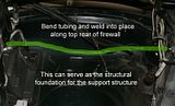
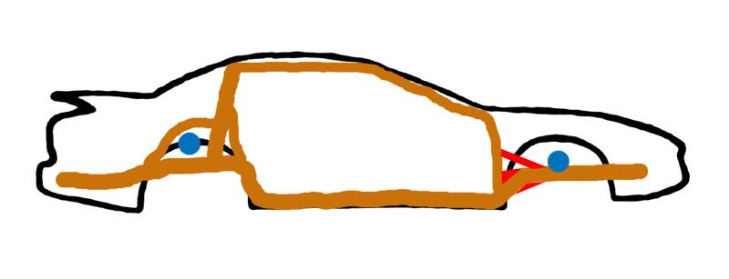
One idea I had a while back was to bend up a strong bar and weld it on the ends of the firewall where I can weld without removing the dash. Then carefully tack the bar in certain areas along it's length and spray with water right away to keep from setting anything on fire. It's risky though.

Last edited by JasonWW; 03-27-2011 at 10:10 AM.
03-27-2011, 09:49 AM
#9
Here is the most efficient way to brace the front and is what you were saying Leadfoot. Adding the red bar.
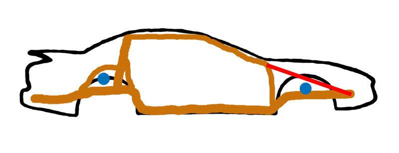
The downside is needing to strip the dash out. I think I can get almost the same strength by keeping the welding points lower, thereby not having to remove the dash.
A C6 frame for comparison:
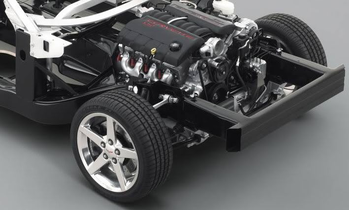
I thought about replacing the front frame rails with 2x4 tubing, but I don't think it's necessary. The work involved wouldn't be worth it. I think I can beef up the stock rails and be fine.
The downside is needing to strip the dash out. I think I can get almost the same strength by keeping the welding points lower, thereby not having to remove the dash.
A C6 frame for comparison:
I thought about replacing the front frame rails with 2x4 tubing, but I don't think it's necessary. The work involved wouldn't be worth it. I think I can beef up the stock rails and be fine.
Last edited by JasonWW; 03-27-2011 at 10:11 AM.


 03-27-2011, 03:05 PM
#16
Curve some tubing to follow that fender support piece so it runs just outside of the strut mounts. Save the plate that the struts bolt to and bend another piece of tube to hold that plate in its place. Making a "P" shape so that the plate is inside the loop of the "P." A 10-point cage will give structural integrity if you weld those front tubes to the rest of the cage. A STB will really help after all that too. The up side of my design is that you could weld the loop of the "P" higher to lower the car! Best way is to design all this in a "working drawing" schematic. AutoCad would be a good program to use to do that and as long as you keep it scaled correctly, you can break off the individual pieces of tubing and it'll give you the exact length, location of bends and degree of curves.
03-27-2011, 03:17 PM
#17
Curve some tubing to follow that fender support piece so it runs just outside of the strut mounts. Save the plate that the struts bolt to and bend another piece of tube to hold that plate in its place. Making a "P" shape so that the plate is inside the loop of the "P." A 10-point cage will give structural integrity if you weld those front tubes to the rest of the cage. A STB will really help after all that too. The up side of my design is that you could weld the loop of the "P" higher to lower the car!

That's why the entire shock tower is coming out. I'm not installing a 10 point cage either.
BTW, with a stock suspension the shock/UCA arm mount can not be moved higher due to the brake master cyclinder.
Last edited by JasonWW; 03-27-2011 at 03:23 PM.
03-28-2011, 11:12 AM
#19
Right now the goal is to be able to put the K-member on the ground.
With the trick suspension I'm building it should be no problem.
The tires will be close to the hood, but with the shock towers gone, they should have plenty of room.
The exhaust will be tucked up high, so that's no problem.
The one thing bugging me is that with the K-member on the ground, the side skirts will still have a 2" gap.
One solution is to move the K-member, engine, and trans up. Unfortunately the AC stuff is tightly pressed against the transmission tunnel so I can't cut it out and raise it. (Edit, see below) I've got poly motor and trans mounts and it really helps keep them from moving around so I might be able to raise the drivetrain up a little bit. I need to crawl under there and measure the space.
Another solution is to cheat a little and make some new side skirts that look stock, but extend down a little farther
I may do a bit of both.
Last edited by JasonWW; 03-28-2011 at 12:30 PM.
03-28-2011, 12:04 PM
#20
Correction:
Theres about a 1" gap between the trans tunnel and the AC components.
There's roughly 1" of clearance between the trans and tunnel. So if I raise the tunnel 1" and then raise the engine/trans 1.5" that will just about get the job done.
I might even be able to "raise" the tunnel with hydraulic pressure and squeeze in the sides to lift the top. Hmm?? Maybe.
Last edited by JasonWW; 03-28-2011 at 12:32 PM.