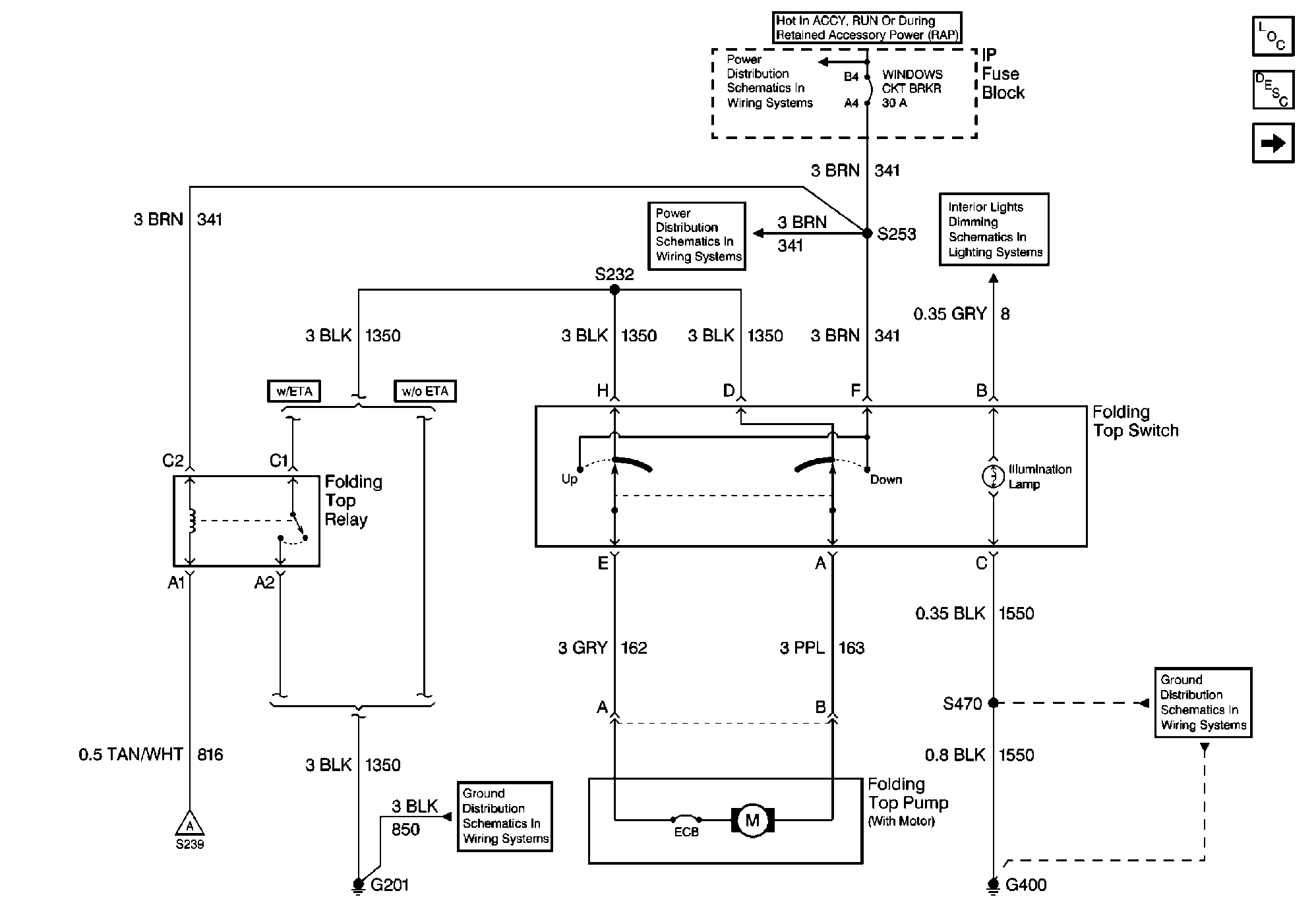
Convertible Top Switch Wiring Diagram
#4
B - illumination
C - ground
H, G - ground
F - +12 volt feed I would fuse this 10 amps probably and make it ignition controlled
E and A to cutout, if it works backwards of what you want then swap them
C - ground
H, G - ground
F - +12 volt feed I would fuse this 10 amps probably and make it ignition controlled
E and A to cutout, if it works backwards of what you want then swap them
#5
Ungrounded Moderator
iTrader: (4)
All wires marked BLK go to ground.
You need B and C to have power and ground for switch illumination - the power would come from the dash illumination... gray wire from the dimmer switch.
The switch is designed to reverse polarity on the two output wires A and E. When in the neutral position the outputs are connected to grounds D and H. In the "UP" position, power from F goes to E and A still goes to ground through D. In the "DOWN" position, power from F goes to A and E goes to ground through H.
#7
Needed to pop this thread up because I need to troubleshoot my top switch. Searched the SVC manual with no luck. Can anyone share the pin diagram for the power top switch on the ‘97-‘02 f-body convertible…..?
Trending Topics
#8
Ungrounded Moderator
iTrader: (4)

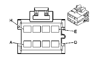
Convertible Top Switch Connector
A - purple - down output to motor
B - gray - switch illumination power
C - black - switch illumination ground
D - black - up motor ground
E - gray - up output to motor
F - brown - input power from windows circuit breaker
G - unused
H - black - down motor ground
The motor goes up or down based on reversing polarity on the purple and gray wires (A and E). For down, power from the brown wire (F) is passed to the motor through the purple wire (A) which then grounds via the gray wire (E) through the switch to the black wire (H). For up, the power flows in the opposite direction... through the gray wire (E) to the motor and to ground via the purple wire (A) through the switch and to ground on the black wire (D).
The simple test is to unplug the switch, apply power to the purple wire and ground to the gray wire - the top should go down. Switch the power and ground and the top should go up. (Make sure you use the correct gray wire in position E otherwise you'll just light up the dash.) Check that you have incoming power on the brown wire. If those things check out but the top doesn't work using the switch then you can be sure the switch is the problem.
I noticed that my original post (#2) no longer had the wiring schematic so I replaced it (the web site which had originally hosted it was shut down).
#9
Thank you , Sir...!
My top stopped going up ( but works fine going down ) everything else checks out but the switch.......Now to ohm it out and start looking for a replacement if needed.....
My top stopped going up ( but works fine going down ) everything else checks out but the switch.......Now to ohm it out and start looking for a replacement if needed.....
#10
Did a quick voltage test on the switch using a 9v battery. With + on terminal F to supply power. From terminal A to ground read 8.3vdc with the switch in the lower position. From terminal E to ground read only 3.5vdc with the switch in the raise position.
Going to try your test procedure next - but I'm thinking a bad switch......
Did an ohm reading on the switch and from terminals F to A with switch "down" I got .5 ohm. From F to E with switch "up" I read 20M ohm. I saying bad switch. Odd because the car only has 18k original miles........
Going to try your test procedure next - but I'm thinking a bad switch......
Did an ohm reading on the switch and from terminals F to A with switch "down" I got .5 ohm. From F to E with switch "up" I read 20M ohm. I saying bad switch. Odd because the car only has 18k original miles........
Last edited by Bondservant2; 09-14-2021 at 02:52 PM.
#11
Ungrounded Moderator
iTrader: (4)
I’m trying to check the switch with an ohmmeter and the switch diagram is confusing. From the diagram my switch has no lug at F or (if flipped 180-degrees) no lug at C. Also - the diagram is showing the switch upside down. In other words the locking tab for my switch is on the bottom - the direction the switch would move to lower the top.
The connector is shown with the locking tab only for reference to locate the correct pin labels. It has nothing to do with the actual physical orientation when installed. The idea is that you can rotate the physical connector (or the switch when removed) to match the orientation of the diagram so you can determine which pin is which. That's also why I included the wire colors for addition confirmation of each pin.
I could but why would you want to do that when the diagnostic tests I suggested will give you the answer in just a few moments? Besides, testing the switch by itself only tells you if the switch is good or bad whereas testing by powering the motor also tells you if the motor is good or not.
Did a quick voltage test on the switch using a 9v battery. With + on terminal F to supply power. From terminal A to ground read 8.3vdc with the switch in the lower position. From terminal E to ground read only 3.5vdc with the switch in the raise position.
Going to try your test procedure next - but I'm thinking a bad switch......
Did an ohm reading on the switch and from terminals F to A with switch "down" I got .5 ohm. From F to E with switch "up" I read 20M ohm. I saying bad switch. Odd because the car only has 18k original miles........
Going to try your test procedure next - but I'm thinking a bad switch......
Did an ohm reading on the switch and from terminals F to A with switch "down" I got .5 ohm. From F to E with switch "up" I read 20M ohm. I saying bad switch. Odd because the car only has 18k original miles........
#12
Yes - I did figure out that the diagram you posted was indeed the wiring connector TO the switch....ooops. (reading is essential).
I think the 20Meg reading is indicative of worn out / bad contacts as I was able to get a small voltage reading but high resistance. I was lucky that someone had just listed a switch on ebay (used but I was told it works) and got it ordered so I should know more in a few days. As I mentioned the top works fine going down - so I would believe its not a motor problem.
As a side note to fellow convertible owners. If you have to use the pressure relief valve to raise or lower your top manually expect to lose some of the fluid from the system. You'll see a spot behind the rear drivers tire where it will drain from the trunk area under the pump. Just be sure to close the valve after use and watch the fluid level in the pump. That has happened the times I raised the top manually.


