When you click on links to various merchants on this site and make a purchase, this can result in this site earning a commission. Affiliate programs and affiliations include, but are not limited to, the eBay Partner Network.
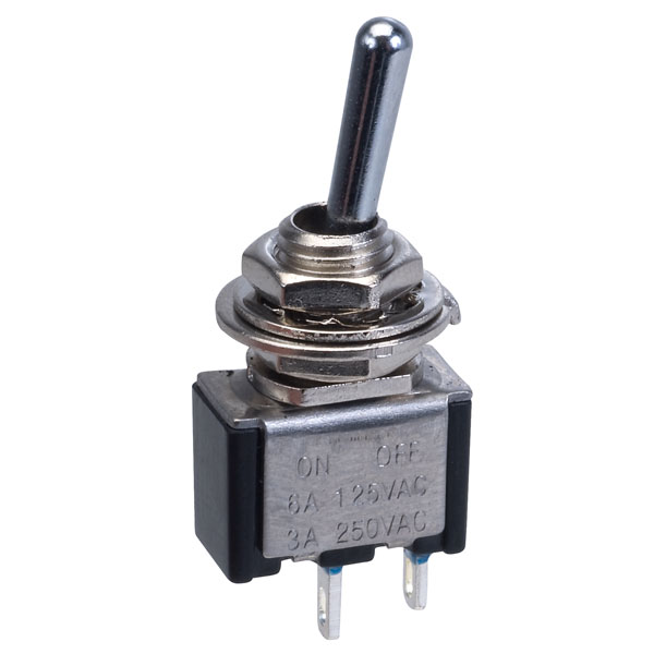
I would like to purchase an accessory light that has white and amber light functionality. It also has some strobe features I'm not interested in, but this light is the one I've determined I want. It comes with the switch pictured below, and also pictured below is how it is wired. For reasons, I hate the switch and don't want to use it. Would it be possible to wire this to a simple toggle switch (or two) and maintain functionality? Hopefully someone that understands wiring better than myself will be able to answer.
Don't waste your money on the harness.. all you need is 1 good 3 position switch..
I believe it would be a "On-OFF-On" or "3 position single throw switch" you can buy them up to 50A I'd check the draw on the light and just size accordingly..
If its over 20A I would consider a pair of relays. (1 per switch. )
Check sources like Mouser. Nothing causes more issues than cheap electrical parts..
From: Jacksonville, FL (originally from Toronto Canada)
I doubt toggle switches, or a SPDT switch as pdxmotorhead describes, will work for this application. The ad is short on electrical details because they expect it to be plug-and-play but it appears that switch 01 is either push on/push off or a momentary switch which takes advantage of latching relay capabilities. That can be replaced with a SPST toggle switch or an aftermarket push on/push off or momentary switch depending on whether you plan to keep the relay and harness or not. However, switch 02 is almost certainly a momentary switch which allows you to cycle through the different modes with each press so you'll need to replace it with a similar momentary switch.
You may lose the memory capability if it is built-in to the switch module but I doubt it. All of the strobe light modules I've installed have had the memory in the light module rather than the switch... many don't even come with a custom switch included yet still retain the selected mode between uses.
Wiring with aftermarket switches should be easy. The light module can actually be grounded (black wire) anywhere convenient such as a bolt near where it's mounted - there is no reason the ground has to be run back through the relay or switch. The power wire (red) is the one which must be switched. Depending on whether you want to be able to use the light with the ignition off, you can connect a toggle switch to battery power or to an ignition switched power source. The yellow mode wire is the tricky one. It can be designed to trigger a switching modes based on being grounded or on having power applied. It would be best to find out from the manufacturer (if they will tell you) but you can always test it by powering on the light and then touching the yellow wire to ground (ALWAYS use ground for the first test because it won't damage the light if it's the wrong choice). If the mode changes each time you touch the yellow wire to ground then you can simply connect the yellow wire to ground through a momentary switch. If the mode doesn't change then try the same thing only applying power to the yellow wire momentarily to see if that makes the mode change. Then you can wire the yellow wire to power through a momentary switch. It's really a 50/50 shot whether the mode switch yellow wire requires ground or power - I've seen them both ways. But again, ALWAYS try ground first!
Thanks for the response. I haven't ordered this light yet because I wanted to make sure I would be able to rewire the switch. Have to use their switch is a deal-breaker for me with this product. I believe I still have an extra momentary switch (they sent me 2 by mistake) from my dakota dash install. This switch is a toggle/button where (excuse my ignorant terminology) the switch rests in the middle. Pushing it up is a feature, and holding it up is a feature, pushing it down is a feature, and holding it down is a feature. Would this switch work in it's place? (sorry, can't get it to resize)
From: Jacksonville, FL (originally from Toronto Canada)
Unfortunately, that switch won't work by itself because of its momentary nature. It's an ordinary SPDT momentary switch (i.e. ON-OFF-ON) and the ability to have two functions at each end is not in the switch but in the device it's connected to... just like the difference between a tap and a long press on a phone or tablet icon.
The light requires continuous power to stay on - it will turn off as soon as you take away power - so a momentary switch can't provide that by itself (unless you want to hold the switch for the entire time you want the light on ). You'll need a latching relay or a module to convert a momentary power signal into a continuous power supply for the light.
Latching relays are a good choice if you are able to provide two different signals (one for on and one for off) or you can reverse polarity of a single input (for example, power for on and ground for off). That would involve some tinkering to get it to work in this case. One way would be to use that switch you have but wire it so pressing one way turns on the light - latches the relay - and pressing the other way turns off the light - unlatches the relay. Then you would still need a separate momentary switch for mode selection. Many latching relays are electronic devices designed for circuit board installation but there is an enclosed 12V latching relay module that provides 8 amps of output and is very easy to set up. It costs $21 on Amazon... search for "latching relay 12v dc".
An alternative is a trigger module like the PAC TR-7. It provides many useful functions but the one you would use in this case would be the latch and unlatch function (#3). This lets you have a single trigger pulse turn on a steady power output and a second trigger pulse on the same input turn off that steady power. That would allow you to use your switch for both power on/off and mode select. You could press once on the I side to turn on the light and press again to turn it off, leaving the II side for changing the light mode. The module costs almost $30 on Amazon but doesn't produce enough output to directly power the lights... you would still need to add an ordinary 30A automotive relay to provide enough current (the module would be wired to trigger the relay). Personally, I think this is the more elegant solution because it uses only the single switch you already have but it involves a little more wiring behind the scenes. Let me know if you go this route and I can assist with the wiring if you like.
Thanks for the great information. While I'm very tempted to wire this up with the PAC TR-7 as you mentioned, for this project I think it would be best for me to stick with removing the provided 2-button switch controller and wiring in two separate switches. If I understand what you stated correctly I could do this by using two SPST switches. One would be a toggle switch which would turn the light on and off, and one one be a momentary switch which would select the features (strobe, white, amber, etc). Is this correct?
From: Jacksonville, FL (originally from Toronto Canada)
Yes, that is correct. You'll wire the toggle switch to provide power to the light via the red wire. You'll wire one terminal of the momentary switch to the yellow wire of the light and the other to either ground or power depending on which it requires as described earlier.
OK, got it. Thanks, I wanted to clear that up before I actually ordered it. I'm placing the order now and hopefully have enough information from this thread to wire it up without burning it up.
It got a little more complicated. I just got the light in today and found out that the mode requires both the flood lights and the light bar be on at the same time. I want to wire it so that I can have all of them on at once, or only the light bar by itself, and maintain the functionality of the "mode" button if either one is selected. The first picture is how the instructions show the system is originally wired. The fact that the lights have a ground wire that seems to run back to the relay has me a bit confused, because in looking at the relay that came with the setup, it only has 4 prongs on it. Normally, I would expect the ground wire to go ground to chassis after exiting the light. I'm not sure exactly where it goes when the ground goes back into the harness and returns to the relay.
This is what I've got so far in trying to figure out how to wire it up to have the option of having the light bar by itself, or light bar with flood lights at the same time. In the diagram below, I've added a second relay to power the flood lights. A few questions...For now, I'm assuming the yellow wire going to the momentary switch grounds to activate rather than goes to positive. I am assuming if I splice the yellow "mode" wire so that it runs to both sets of lights it won't harm the flood lights for the "mode" button to be spliced in even when the flood lights do not have power going to them (not lit). Also, I can't figure out how to splice the flood lights into the SPDT switch so that when the switch is in one position they all come on together and when it's in the second position only the light bar will come on. So far any way I've thought about it will cause all the lights to come on when the SPDT switch is in both positions, so I know my SPDT wiring shown below isn't correct. I'm not sure how to wire that part, but I feel like changing to a DPDT switch will allow this, I just can't figure out how. Also, I'm still confused by all the ground wires coming from the lights that are running back to the relay.
Last edited by Vetteman61; Nov 19, 2021 at 10:22 PM.
The led's are likely all BI-color, When you energize 1 leg and ground the black you get white, when you energize the other leg yellow..
OR energize red and it turns white ,, add power to the yellow wire and you can flash it.
I'd open up the switch module and see if there isn't a small IC in there that's doing the switching for the flashing modes..
The relay in the original package is likely a SPDT like a standard Bosche possibly with a latch circuit. (If its got the same numbers on the bottom and 5 terminals its prob a bosche or a bosche clone.
The grounds are wired like they are likely because the most common cause of lighting problems is a bad ground, bring all the grounds to a singal (-) and no ground problems.
There are a ton of small COBB style Led combinations,, 1 color/2 color/tri-color combinations are endless.
Thanks for the reply. I'm pretty sure that each LED is only one color because this light bar only has white and amber, and there are both white and amber LEDs on the bar, separately. The supplied relay only has 4 terminals, which has me curious as to where they're all going. You may be right in that they are all leading back to the terminal on the relay that goes to ground, just to ensure proper grounding and no problems. Now that you mention it, I suppose if I was making an LED light for the masses, I might do the same to prevent improper grounding and returns of the product.
Yep was my best guess,, hard to tell without seeing it.
4 terminals is a standard spst relay.. "normally" so that really makes me think the flash is all being done in the switch "pod"
2 pins for the relay activation and 2 pins for the circuit your switching.
From: Jacksonville, FL (originally from Toronto Canada)
The flood lights are a variable which was not shown in the original ad you posted. That could complicate things or it may not make any difference depending on how they're set up.
If you hook everything up at the bench using the factory harness, what does the mode button do? Does it cycle through all combinations of the light bar and flood lights and also of the colors and strobe effects? Or does it only cycle through colors and strobe effects, expecting that all of the lights will be powered all the time? Have you actually tested the light bar by itself without the flood lights connected to see if the modes still work? If you can apply power and ground to the red and black wires of the light bar and then change modes by touching the yellow wire to ground then you know there is nothing special about the included switch module. You can do that at your battery using jumper wires with alligator clips. If it doesn't work then you'll know that the "intelligence" is in the switch module rather than in the light... although every one I've worked with has always had the intelligence in the light and not in the switch. That allows using switches other than the one that comes with the lights.
If the switch module really is the controller then I suppose one possibility would be to open it up and connect the wires for your own switches to the built-in switches in the module and then hide the module under the dash somewhere.
I did some bench testing this week. I got it to work, but it isn't wired as I showed in the picture above. I added another relay, a DPDT on/off/on switch and a SPST on/off momentary switch. I cut the controller off and after jumping the middle prong of the DPDT to the other side, was able to get the light bar to activate separately, or in conjunction with the flood lights. Also, the function of the lights (white/amber/white strobe/amber strobe/amber and white/ amber strobe alternating with white strobe) can be isolated to the light bar or the strobes because each light maintains its memory. Then means if you cycle the mode of the lightbar while power is not applied to the flood lights, the floods will retain their setting and stay on that setting when they are powered back on again. This allows me the ability to have flashing amber flood lights while also having the light bar to shine bright white light, in the case of a roadside assistance situation. Now that I have it working on the bench I can wire it permanently into the vehicle.
Thanks, I appreciate the help. I would have had no idea what terms to research for the switches and figure that out without the explanation and terminology. Thanks
6 Common C5 Corvette Failures and What's Involved In Repairing Them
Slideshow: From wobbling harmonic balancers to failed EBCMs, these are the issues that define long-term C5 ownership and what repairs typically involve.
Retro Modern Bandit Pontiac Trans AM Comes With Burt Reynolds' Autograph
Slideshow: A modern Camaro transformed into a retro icon, this limited-run "Bandit" build blends nostalgia with brute force in a way few revivals manage.
Top 10 Greatest Cadillac V Series Performance Models Ever, Ranked
Slideshow: Cadillac didn't just crash the high-performance luxury vehicle party, it showed up loud, supercharged, and occasionally a little unhinged...
Coachbuilt N2A Anteros Is an LS2-Powered C6 Corvette In Italian Clothes
Slideshow: A one-off sports car that looks like a vintage Italian exotic-but hides a C6 Corvette underneath-just sold for the price of a new mid-engine Corvette.


 ). You'll need a latching relay or a module to convert a momentary power signal into a continuous power supply for the light.