When you click on links to various merchants on this site and make a purchase, this can result in this site earning a commission. Affiliate programs and affiliations include, but are not limited to, the eBay Partner Network.
I'm working on a 2000 Camaro SS, automatic. I'm wanting to keep the BCM while removing the factory ECM and gauge cluster, swapping them out for a Holley Dominator and Tinker Dash. I also want to remove the factory relay boxes under the hood and install an aftermarket relay/fuse box behind the dash. The interior fuse box (IP fuse panel) will be retained and all the associated wiring with it. I'm deleting the cruise control, airbags, EGR, EVAP, AIR, traction control, & ABS.
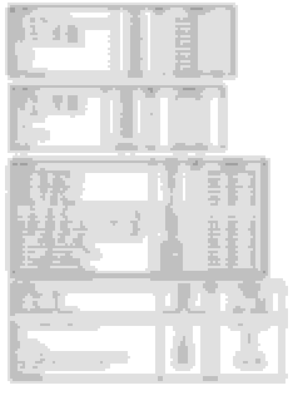
I reorganized the main power distribution and interior/exterior lighting schematics found in the factory service manual so that I could see them in a single snapshot view. Links are below.
I'm still in the planning phase, but my thoughts after reviewing the above files are to:
1. Use an in-line fuse to replace the function of the IGN MaxiFuse 50A.
2. Use a new splice in place of factory splice S183. The wires coming off that splice are shown in the diagram below. Run the wires to a 70A relay, a 35A relay, and Pin B on the Ign Switch.
3. Replace Fusible Link Z with a CB. Remove the male MP280 terminal from in-line connector C200B Pin B6 and place it in an MP280 7 way 12110753. Mate the connector to a female terminal in connector 12110751 and run that side to a E39-20A 20A circuit breaker.
4. Replace Fusible Link F with a CB. Follow the same steps in step 2 above, using the male terminal found at C200B cavity C2.
5. Replace Fusible Link F with a CB. Follow the same steps in step 2 above, using the male terminal found at C200B cavity C1.
6. Replicate the function of the I/P-1 MaxiFuse 40A using at ATC 40A fused housed in an aftermarket fuse block.Follow the same steps in step 3 above, using the male terminal found in C200D cavity D2.
7. Replicate the function of the I/P-2 MaxiFuse 40A using at ATC 40A fused housed in an aftermarket fuse block.Follow the same steps in step 3 above, using the male terminal found in C200D cavity B4.
8. Replace the STRTR MiniFuse 15A with an in-line 15A fuse. Remove the male MP280 terminal from in-line connector C200D pin C5 and place it in an MP280 7 way 12110753. Mate the connector to a female terminal in 12110751 and run that side to PNS pin E.
9. C3 pin C11 on the BCM is a micro pack 100 series female. Part number is 12146447.The wire going between it and leading to starter relay pin 86 is 20 AWG. Re-pin and run the new wire to an aftermarket starter relay.
10. Run a 10 AWG wire from pin 85 on the aftermarket 70A relay to splice S185. Use 63562-1 for this splice. Retain the 2 factory wires that were in the old splice and place them into the new splice, for a total of 3 wires that will need to be crimped. Pin 87 on the 70A Relay Module will go to the main stud on the aftermarket fuse Block #1.
11. Replicate the function of the ENG SENS MiniFuse 20A. Use an aftermarket fuse in the aftermarket fuse block #1 and run it directly to C2 Pin C on the TCC switch. The ENG CNTRL fuse can be omitted, since all the components it is wired to are omitted from factory ECM control, like the transmission, factory A/C, ETC, EVAP, etc.
12. For the Horn, take the Dark Green wire circuit 29 that leads to the horn. It goes into a MP150 Sealed Female part 12052644 and the Dark Green wire is Pin B, which goes into that connector using female terminal 12084200. Run a new 20 AWG wire and route it to pin 87 on Relay #3 in the Bussmann. The Horn MiniFuse 20A can be omitted, as relay 3 in the Bussmann is tied to fuse F5. Route the wire coming off pin 85 of Relay #3 to the Horn Button. The Horn relay is a ground switched relay, rather than a positive switched, so needs wired correctly with Pin 86 and 30 connected within the Bussmann, and Pin 30 connected to fuse F5.
13. The only relay contained in Junction Block 1 or 2 that ties to the lighting system is theFog Lamp relay. So I'll run a new Fog Lamp relay will be in a Bussmann aftermarket box. Locate splice S150. Make a new splice here using a 20 AWG wire routed from that splice to Pin 30 on the new relay. Next locate splice S160. Make a new splice here and run a 20 AWG wire to Pin 87 on the new relay. Locate the fog light switch. Run a 20 AWG wire from pin A on that switch and route it to Pin 86 on the new relay. Pin A is a 12064971 MP 150 female terminal. Route a 16 AWG wire from pin F on the Fog Lamp Switch to Pin 85 on the FOG Lamp Relay. Pin F is a 12047767 MP 150 female terminal.
14. The brake switch must be connected to the Holley Dominator. I'll be using J4 pin B16. It’s an 18 AWG wire and you can tap into connector C220 pin D and run it from there to J4 pin B16. C220 is located in the IP to engine harness, under the right side of the IP, behind the knee bolster. It is a 10 cavity Metri-Pack 150 connector. Female terminal is 12047767 and male terminal is 12047581 for reference.
So basically we are looking at de-pinning 6 wires from an inline connector and putting them into an aftermarket MP280 connector, in this case a 12110753 / 12110751, and running some relays.
To free up room for the aftermarket Bussmann Relay box and aftermarket fuse blocks, I'll be using a Vintage Air system to replace the factory HVAC parts. Jim TA has a very nice write up on this HERE
And if you are wanting to run a Holley Terminator, JimTA has a thread on it HERE
Parts:
Eaton Bussmann 15305-5-2-4 (This only has a single busbar, so that it's possible to use ground switched relays)
Busbar
MSD 4 way solid state relay
Leash Big Dog Fuse holders (2 of these)
Leash HO 70A relay
15A and 60A in-line fuses
Metri-pack 280 7-way connector
Deutch DTM, DT, DTS to use as quick disconnect for wires coming out the Bussman
Racetronix Dual Fuel Pump and Fan Harness
Some of the terminals and connectors I'll use are shown on tab "B" CLICK HERE
Tab "A" contains many other terminals and connectors and part numbers. Tab C contains every single circuit that passes through either the P100 or P101 grommets. Much easier than searching through all the pages of the FSM to see what passes through the firewall....
Factory Connector Pinouts (some not all) CLICK HERE
S183 - In the forward lamp harness, approximately 10 cm (4 in) from the engine wiring harness junction block 1 breakout. (New Splice needed)
S185 - In the forward lamp harness, at the engine wiring harness junction block 1 breakout (New Splice needed)
S150 - In the forward lamp harness, approximately 16 cm (6.3 in) from the windshield washer pump breakout (New Splice needed)
S160 - In the forward lamp harness approximately 4 cm (1.6 in) from the electronic throttle control (ETC) module/cruise control (NS needed)
S254 - In the IP harness, approximately 8254 7 cm (2.8 in) from the main branch into the C200 breakout.
What the rewire will essentially look like:
Last edited by 5.7stroker; 07-02-2024 at 11:40 AM.
i didnt read everything, but holy cow you should look into getting a r3 or r5 with a pd16 and eliminate all the stupid relays and fuses and move into the 21st century.
i didnt read everything, but holy cow you should look into getting a r3 or r5 with a pd16 and eliminate all the stupid relays and fuses and move into the 21st century.
that one is tiny you would need a bunch of them. the haltech stuff would be a complete ecosystem and is extremely programmable and everything would be done in a single, cohesive, software platform, you even program everything through a single piece of software talking to the ecu. you dont have to configure the PD16 or keypads individually. same if you use a haltech dash, which adds extra inputs, but im sure the tinker dash is fine.
if you are stuck with the holley idea, take a look at the smartwire. it would cost more and be quite a bit less feature and power capable, but it would work together. for a complete rewire like youre doing, it would be hard to beat a haltech system in my opinion. i did the same with my chevelle last year. its rewired end to end and there are zero relays in the car and the only fuse is for the couple items i wanted to be powered all the time instead of just when ignition is on.
just looked closer at the jdr pdm-5 and i wouldnt use one of those if it was free. adjusting current limits with trim pots and active high and low using dip switches, yikes. these days its silly not to just get a system that communicates over can instead of a bunch of discrete wires. at least with smartwire you can sorta program it over usb even though the software gives me flashbacks to the late 90s.
IDR is coming out with a PDM12 in a few months which is larger, not sure on all the details. Going to call them to see what all it entails and compare it to the Smartwire. I’d go with Haltech but my tuner is a Holley guy.
My thought was by keeping the factory IP panel fuses and most of the factory body harness and factory BCM wiring, it's just a matter of tying into those fuses/wiring and replicating the function of the starter relay, ignition relay, fog lamp relay, horn relay two 40A fuses that lead to the IP fuse panel, and the 3 fusible links. That of course entails using a small factory relay box and a fuse block that can house 12 fuses with dual bus bars for switched ign and constant power (or 2 smaller fuse blocks), to house the larger ATC fuses since the Bussmann is limited to 30A ATM fuses. If a PDM can be used while keeping the holly and just remove the Bussmann relay box and Leash ATC fuse boxes to simplify the wiring, I'm all for it. I have wiring harnesses with built in relays/fuses into the harnesses for the fuel pumps and fans.
Last edited by 5.7stroker; 07-02-2024 at 04:01 PM.
with the level of effort you are putting in, these days its not a lot more cost, if at all, to go all solid state. relay boards and connectors and **** add up fast. and all that stuff doesnt weigh nothing thats for sure.
sticking with holley from a tuner perspective makes sense but it will really limit your pdm possibilities. id still try to find something that uses can and solid state if possible, it would be well worth it in the end.
the hardwire stuff might also be worth a look https://www.hardwire-electronics.co....ct-page/pdm-25 they appear to have a holley can bus config available
good luck.
I'll take a look at that unit! Thanks again for your perspective on this.
 07-02-2024, 11:24 AM