


need help with switch options?

Thread Starter
9 Second Club
iTrader: (11)
Joined: May 2005
Posts: 4,507
Likes: 5
From: in your closet
Originally Posted by WhiteBird00
The Firebird had one with the convertible switch and traction control switch there. It might fit a Camaro.
Thread Starter
9 Second Club
iTrader: (11)
Joined: May 2005
Posts: 4,507
Likes: 5
From: in your closet
Originally Posted by WhiteBird00
The Firebird had one with the convertible switch and traction control switch there. It might fit a Camaro.
Joined: Nov 2003
Posts: 11,328
Likes: 346
From: Jacksonville, FL (originally from Toronto Canada)
Originally Posted by ls2 bait
i know they will fit, i wonder if the color will match.......
Joined: Nov 2003
Posts: 11,328
Likes: 346
From: Jacksonville, FL (originally from Toronto Canada)
Originally Posted by ls2 bait
do u have a pic of your dash? i want to see where the fog light switch is.
Trending Topics
Joined: Nov 2003
Posts: 11,328
Likes: 346
From: Jacksonville, FL (originally from Toronto Canada)
If you're just looking for a spot to put an additional switch so that it looks factory installed, there is a switch blank under the Camaro logo next to the fog light switch. It is the same size as the ASR or fog light switch.
LS1 Tech Stories
The Best V8 Stories One Small Block at Time

6 Common C5 Corvette Failures and What's Involved In Repairing Them
Pouria Savadkouei
Retro Modern Bandit Pontiac Trans AM Comes With Burt Reynolds' Autograph
Verdad Gallardo
Top 10 Greatest Cadillac V Series Performance Models Ever, Ranked
Pouria Savadkouei
Top 10 Most Powerful Chevy Trucks Ever Made!

Hennessey's New Supercharged Silverado ZR2 Has 700 HP
Verdad Gallardo
Coachbuilt N2A Anteros Is an LS2-Powered C6 Corvette In Italian Clothes
Verdad Gallardo
Awesome K5 Blazer Restomod Comes With C7 Corvette Power
Verdad Gallardo
10 Camaros You Should Never Buy

10 LS Engine Myths That Refuse to Die
Verdad Gallardo Thread Starter
9 Second Club
iTrader: (11)
Joined: May 2005
Posts: 4,507
Likes: 5
From: in your closet
Originally Posted by WhiteBird00
If you're just looking for a spot to put an additional switch so that it looks factory installed, there is a switch blank under the Camaro logo next to the fog light switch. It is the same size as the ASR or fog light switch.
Joined: Nov 2003
Posts: 11,328
Likes: 346
From: Jacksonville, FL (originally from Toronto Canada)
You could hook up a factory convertible top switch through a latching relay for the fan. It could be wired as push up for on and down for off even though it's a momentary switch.
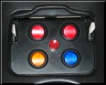
this is just like the factory one but has three big switches and looks kinda factory. i am gonna get one for my electric cutout, and possibly Nitrous if I decide to get some.
http://www.texas-speed.com/shop/item...id=21&catid=31
http://www.texas-speed.com/shop/item...id=21&catid=31
Thread Starter
9 Second Club
iTrader: (11)
Joined: May 2005
Posts: 4,507
Likes: 5
From: in your closet
Originally Posted by WhiteBird00
You could hook up a factory convertible top switch through a latching relay for the fan. It could be wired as push up for on and down for off even though it's a momentary switch.
Joined: Nov 2003
Posts: 11,328
Likes: 346
From: Jacksonville, FL (originally from Toronto Canada)
Originally Posted by ls2 bait
youve caught my attention........how would i go about doing this? any online write ups?
Connect the pins as follows:
A - terminal 86 of your relay
B - dash light power (for switch illumination)
C - ground (for switch illumination)
D - ground
E - 12V+ (ignition controlled)
F - terminal 85 of the relay
G - (doesn't exist)
H - not used
Modify a standard 30-amp relay by soldering a 1 or 2 amp diode between terminals 87 and 85 of the relay. The cathode side (the end with the stripe) connects to terminal 85. This makes the relay "latch" when a momentary positive pulse is applied to terminal 85.
Connect relay terminal 30 to a fused 12V power source. Connect your accessory to terminal 87 (in addition to the diode you soldered there).
Now, when you press the switch up, a momentary power feed is connected to terminal 85 of the relay causing it to trip. Power then flows from terminal 30 through the relay and out terminal 87 to your accessory. A small portion also flows through the diode to terminal 85 in order to keep the relay "latched".
When you press the switch down, the ground for the relay coil is interrupted causing the relay to release and turn off the power to your accessory.

Joined: Nov 2003
Posts: 11,328
Likes: 346
From: Jacksonville, FL (originally from Toronto Canada)
You can still put the original High/Lo switch inline between the relay terminal 87 and the fans. The convertible switch would control on and off while the original switch controlled the speed. I know that might not be the solution you were looking for but there really isn't any way to make a convertible top switch control two speeds. Even if you wired it so that pushing up was high speed and down was low speed there would be no way to turn the fans off.
Thread Starter
9 Second Club
iTrader: (11)
Joined: May 2005
Posts: 4,507
Likes: 5
From: in your closet
why dont u just come down to fort myers and wire this for me  have u done this before? maybe something u would be interested in doing again? if so pm me as i think i got lost half way down the page. im gonna print it out though to take my time and read it good later.
have u done this before? maybe something u would be interested in doing again? if so pm me as i think i got lost half way down the page. im gonna print it out though to take my time and read it good later. Joined: Nov 2003
Posts: 11,328
Likes: 346
From: Jacksonville, FL (originally from Toronto Canada)
I probably won't get down that way until April or May. However, once you have the switch in hand you'll be able to just label the pins and then connect the wires. It sounds more complicated when it's written out than it is once you have the pieces in front of you. If you really need assistance then maybe you can send me the switch and relay and I'll wire them up so you'll just be left with power and ground connections to make.
The switches and plates should be available in grey and black at the very least. There may be a 3rd color, but I'm not sure.
Last edited by JasonWW; Mar 30, 2006 at 12:47 AM.

