When you click on links to various merchants on this site and make a purchase, this can result in this site earning a commission. Affiliate programs and affiliations include, but are not limited to, the eBay Partner Network.
I had a thought. Would I need a late intermediate piston to have enough room for a wave plate? I'm not sure if the early and late pistons are different. I will measure again tonight to see how much clearance I have with no wave plate. I know things are skewed with the clutches being soaked already but at least it would give me another data point.
In hindsight, if I had to do this over again, I would have tried to start with a later model core.
Also, all of the clutches I am using are flat and not waffled
I had a thought. Would I need a late intermediate piston to have enough room for a wave plate? I'm not sure if the early and late pistons are different. I will measure again tonight to see how much clearance I have with no wave plate. I know things are skewed with the clutches being soaked already but at least it would give me another data point.
In hindsight, if I had to do this over again, I would have tried to start with a later model core.
Also, all of the clutches I am using are flat and not waffled
1991-1996 cores will have a slightly taller intermediate piston and a different clutch stack.
1997+ cores use a slightly shorter piston that uses an integrated waved steel (the height of this piston and steel together are aprox. the height of the 1991-1996 piston).
I personally prefer the earlier cores (1995 and 1996 are my favorite) I prefer this lube-system and over-run section for 1,000+.
Any of the cores (regardless of year) can be made to work, by swapping parts from other years though.
No matter what year core I build... I have to use parts from other years.
1991- 1996 units, need a some parts like the carrier and band from the later year cores.
1997 units need some parts like the early style hollow intermediate-shaft, and the over-run section from the earlier year cores.
So the set up of the intermediate clutches has been driving me crazy. I measured it again tonight and realized that I've been measuring it in a difficult way by trying to get the feeler gauges between the top friction and the bottom of the pressure plate. It's a lot easier to measure between the snap ring and the pressure plate instead. With the .070 wave plate with the friction right on top of it, and 3 more steels(4 frictions total, I'm at .089. I feel like .019 will be too tight if I add the steel back on and way too loose without it. Any thoughts?
Note: It would be a good habit of assembling two identical stacks of feeler-gauges (lets say the 0.089" that you used) and insert them in to different positions around the clutch stack, at the same time.
This is a slightly more accurate method of measuring clearance; as not to tilt the backing-plate and get a false reading (larger).
On the Forward and Direct drums where the backing-plate sits on a lip/ ledge of the drum...
Take your top friction and the steel below it out.
Flip them over together.
Placing the top friction on the next lowest friction.
Then the steel at the very top.
The backing-plate will have that steel under it now.
Place feeler-gauges between the steel and the backing-plate.
No worrying about gouging a friction plate now.
I'm a big fan of using spark-plug gap tools.
Like this one.
In so many locations it is easier to get in than a feeler gauge.
And easier than a dial indicator on a flat table.
Agree that installing 2 opposite each other is usually best, but if you can't, I usually compensate with about .002 being the difference from just installing on one side
Work has been very busy so I haven't had a lot of extra time to work on this. I should have the last seals I need and all the steels to set everything up.
Is there a post or quick explanation for air testing? I mostly mean which port to put air to, to test which assembly? Thanks
The center support bolt is where you test the int. clutch
The holes on either side of it are for testing the direct clutch. You likely have one hole plugged for the dual feed. So test at the other one.
The Fwd clutch and overruns can both be air checked on the bench by turning the pump upside down and setting it on top of something. Then assemble the input shaft, OD planet and everything up to the fwd drum.
The OD clutches can be tested via that torx bolt in the case.
The band can be checked via the hole that feeds it in the case. You must have the cover and gasket in place and torqued.
Awesome! I will check the intermediate piston with air tonight and then install the forward and direct. It is probably a bad idea to install the 4th clutch without replacing the seals right? It looks intimidating but I can give it a go if necessary.
Also, I've been using the ATRA 4l80e Manual by Cliff McCormick in addition to the ATSG manual. The ATRA manual has great full color pictures which have been very helpful.
Last edited by Novapat67; Oct 12, 2020 at 05:46 PM.
Well, last night did not go smoothly. First, I air tested the intermediate clutch. It actuated fine but I need to get a better air nozzle as mine was leaking. I suppose it wouldn't actuate if there was a leak at the seals so that should be good.
I soaked the frictions and assembled the direct. I went to install it and realized I had not compressed the sealing rings on the center support enough so it would not slide over. I did compress them with a hose clamp but I didn't slide the direct over them to make sure everything fit ok. I will have to pull the gear train out and remedy this.
For anyone else following along, make sure you bench test everything!
I also started working on my boost valve kit and can't get the old one out. Even after the snap ring is removed, it catches on the bore. I will have to lightly file a chamfer into it so it doesn't catch.
Gas Monkey Built a 6-Wheel Ferrari Testarossa With a Corvette LT4 Engine
Slideshow: The controversial Ferrari F6 swaps its original flat-12 for a Corvette Z06-derived LT4 V8 and sends power to four rear wheels through a custom-built drivetrain.
7 Most Reliable High-Performance Engines GM Has Ever Built
Slideshow:These GM engines didn't just make huge power, they survived abuse, boost, track days, and six-digit mileage with a reputation for refusing to quit.
6 Common C5 Corvette Failures and What's Involved In Repairing Them
Slideshow: From wobbling harmonic balancers to failed EBCMs, these are the issues that define long-term C5 ownership and what repairs typically involve.
Retro Modern Bandit Pontiac Trans AM Comes With Burt Reynolds' Autograph
Slideshow: A modern Camaro transformed into a retro icon, this limited-run "Bandit" build blends nostalgia with brute force in a way few revivals manage.
Top 10 Greatest Cadillac V Series Performance Models Ever, Ranked
Slideshow: Cadillac didn't just crash the high-performance luxury vehicle party, it showed up loud, supercharged, and occasionally a little unhinged...
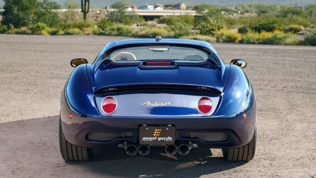
Coachbuilt N2A Anteros Is an LS2-Powered C6 Corvette In Italian Clothes
Slideshow: A one-off sports car that looks like a vintage Italian exotic-but hides a C6 Corvette underneath-just sold for the price of a new mid-engine Corvette.