

2BFAST'S 69 Camaro 4L60E Build
 02-03-2021, 09:01 PM
#61
TECH Junkie

I have been enjoying this thread... You have obtained some very nice parts!!! 
I very much like the 4L79 Input-Drum!
I only wish that it did not have to use custom steel-plates... They can be difficult to get at times.
I may consider having them laser-cut for myself when I can not get them with the drum.
Those Raybestos GPZ friction-plates are also very nice... They are the ONLY other friction-plates that I will use in the STOCK drum for the 3-4 clutch.
Normally I use the OEM Borg-Warner High Energy plates.
I like the Raybestos Stage-1 friction-plates also in the 4L79 drum 3-4 clutch (Stock THM350 Direct clutch dimentions).
Those shafts are supposed to be very nice... I have not been able to do any testing with them yet.
They are WAY over-kill for your 400 HP engine, but there is no harm in that.
I have cryo-treated stock 4L60E shafts surviving at double your power level.
Keep the thread going! Great job!
 02-04-2021, 07:36 AM
#62
I have been enjoying this thread... You have obtained some very nice parts!!!
I very much like the 4L79 Input-Drum!
I only wish that it did not have to use custom steel-plates... They can be difficult to get at times.
I may consider having them laser-cut for myself when I can not get them with the drum.
Those Raybestos GPZ friction-plates are also very nice... They are the ONLY other friction-plates that I will use in the STOCK drum for the 3-4 clutch.
Normally I use the OEM Borg-Warner High Energy plates.
I like the Raybestos Stage-1 friction-plates also in the 4L79 drum 3-4 clutch (Stock THM350 Direct clutch dimentions).
Those shafts are supposed to be very nice... I have not been able to do any testing with them yet.
They are WAY over-kill for your 400 HP engine, but there is no harm in that.
I have cryo-treated stock 4L60E shafts surviving at double your power level.
Keep the thread going! Great job!
Yes, there will be quite a bit in this build that will be overkill. I would rather do it once and be over with it. Dana mentioned the same thing about the cryo'd 4L65e and I did check on a few places that I know of that have been good to me with nice used parts and they said they didnt have it. So I just went with the Sonnax shaft. Then like I said I might as well go with the input shaft and be done with it.
You mentioned you wanted to see the splines on the reaction hub a little earlier in the thread. Did you see the pictures I posted? What are you looking for?
02-04-2021, 07:44 PM
#63
TECH Junkie
Definitely some very nice and Over-Kill parts!
LOL! I did not want to see the splines in the photos that you posted...
I wanted you to look at them; since you asked what the punch markers were for on the two hubs.
After looking at how the output-shaft splines into the hub... what do you think the purpose of those punched dimples are?
I wanted you to tell me what you thought... Instead of giving you the answer.
I would like to start trying to lead you guys to the answers instead of just giving you guys answers.
02-05-2021, 07:28 AM
#64
Definitely some very nice and Over-Kill parts!
LOL! I did not want to see the splines in the photos that you posted...
I wanted you to look at them; since you asked what the punch markers were for on the two hubs.
After looking at how the output-shaft splines into the hub... what do you think the purpose of those punched dimples are?
I wanted you to tell me what you thought... Instead of giving you the answer.
I would like to start trying to lead you guys to the answers instead of just giving you guys answers.
LOL! I did not want to see the splines in the photos that you posted...
I wanted you to look at them; since you asked what the punch markers were for on the two hubs.
After looking at how the output-shaft splines into the hub... what do you think the purpose of those punched dimples are?
I wanted you to tell me what you thought... Instead of giving you the answer.
I would like to start trying to lead you guys to the answers instead of just giving you guys answers.
My question is why does one have 6 and the other only have 2?
02-08-2021, 08:45 AM
#65
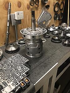
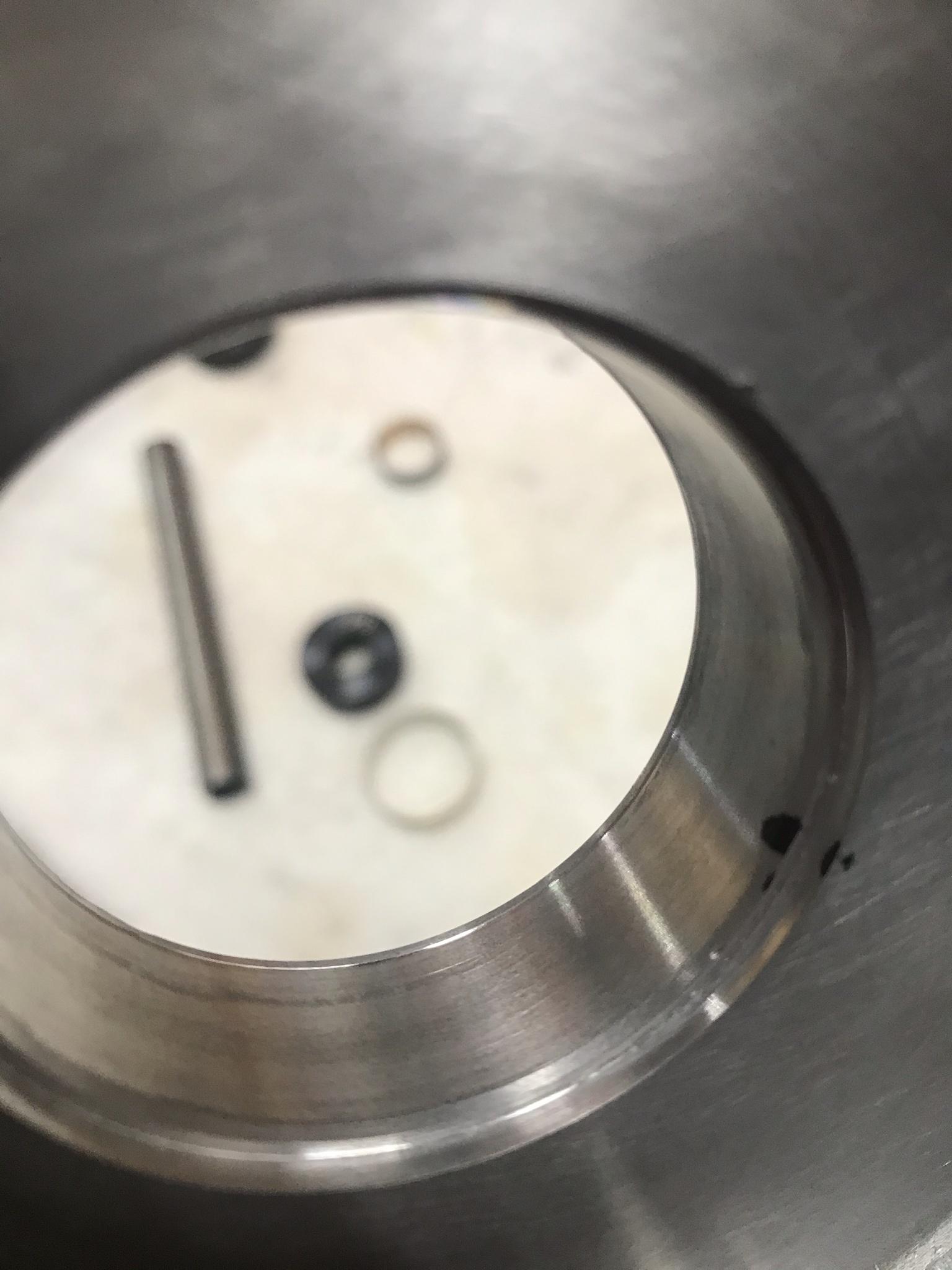
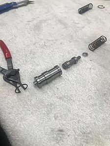
While waiting on the rest of the parts to show up which should be trickling in the next 2-3 days, I did some prepping, continued cleaning, build and vacuum testing the valve body, pressing out and in input shafts ,ect

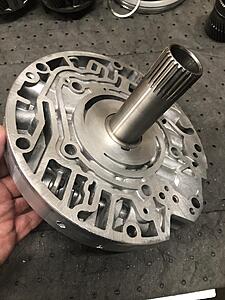
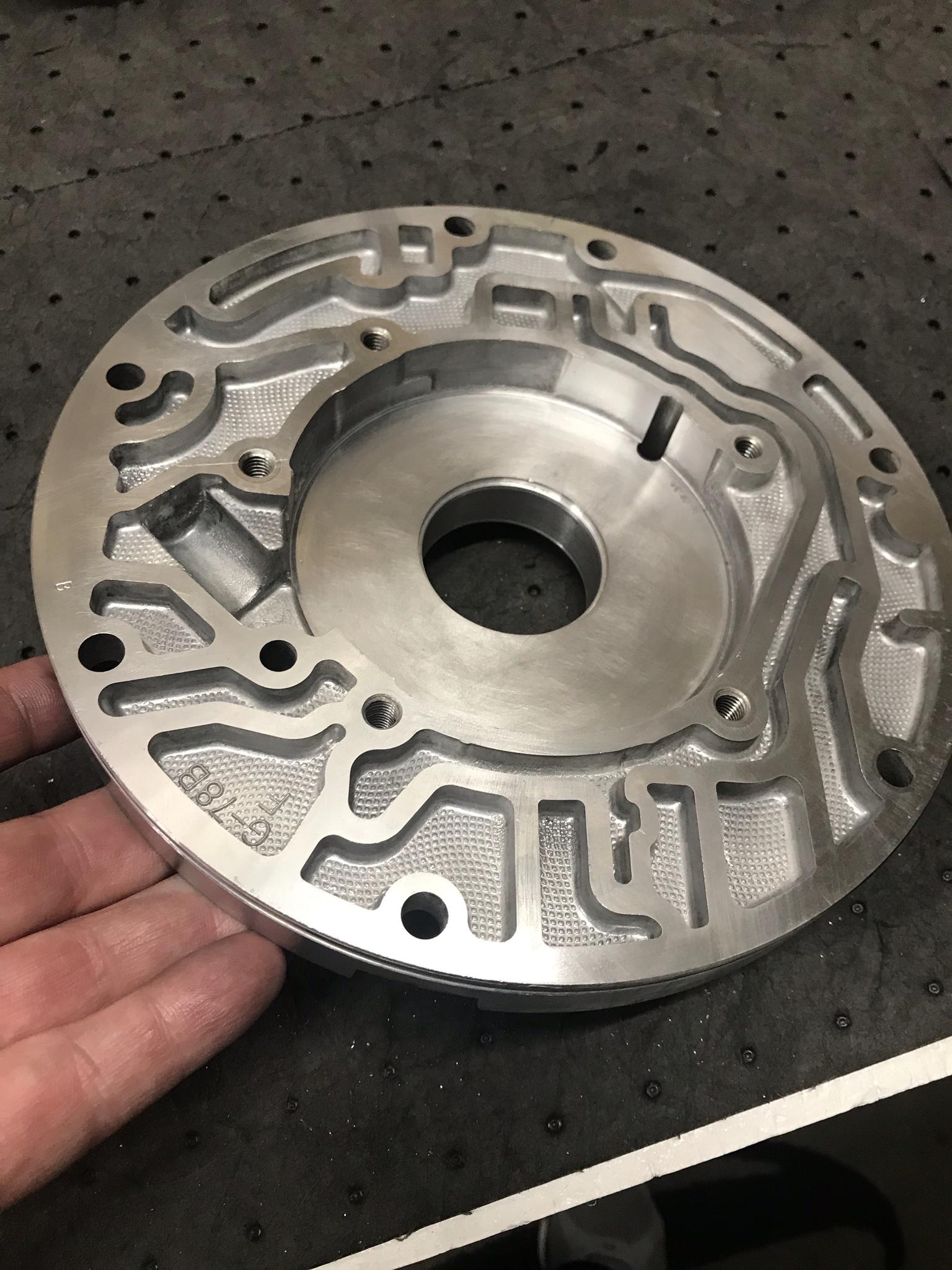
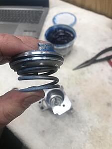
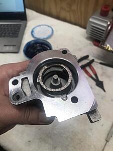
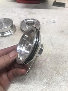
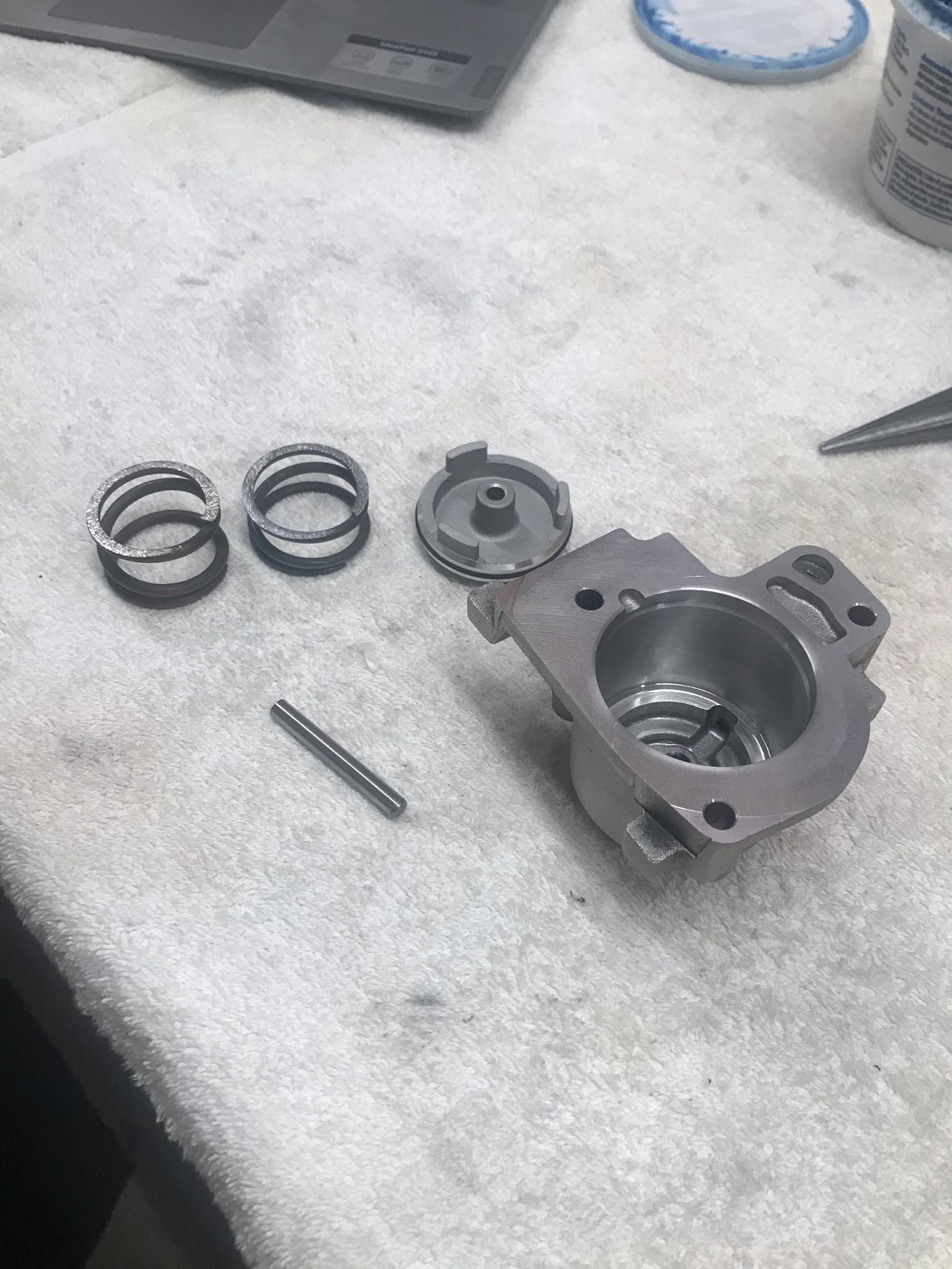
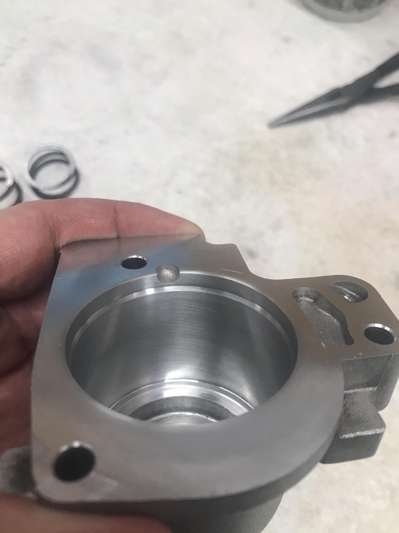
Got the pump all ready to go. Actually vacuum tested it as well with all the factory internals before I took it apart to clean and prep. TCC apply, pressure reg, and boost valve were all at a minimum of 20" inhg. I planned to run the Sonnax 77805E-K TCC apply valve which has a PTFE seal to even further seal that bore as its a drop in valve but had a little issues getting the seal to form. Will work on that further. I will be running a TransGo .500 boost valve when it comes in. More on all that later. Here is the cleaned and prepped pump

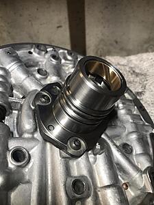
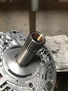
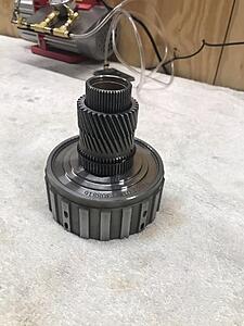
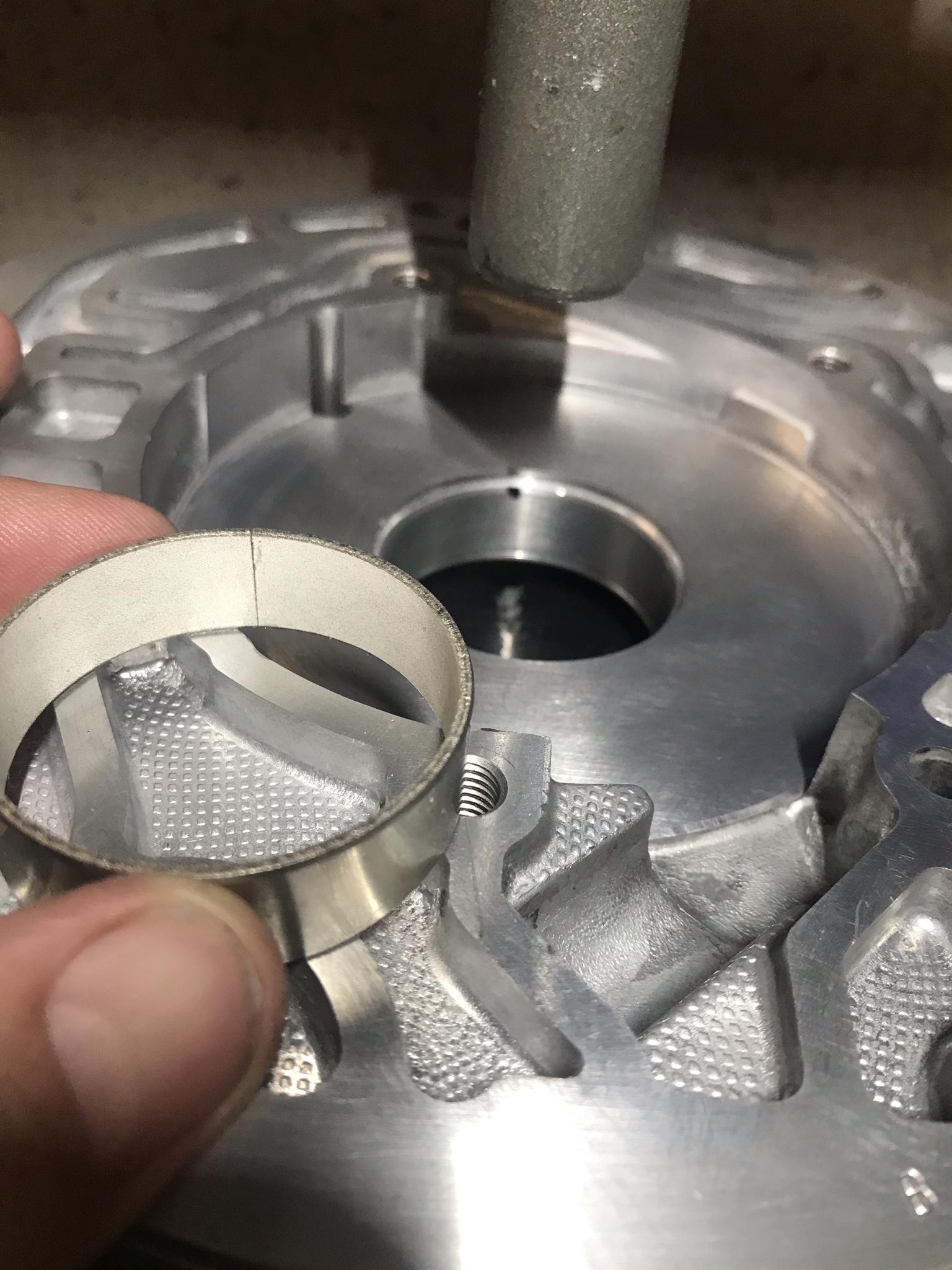
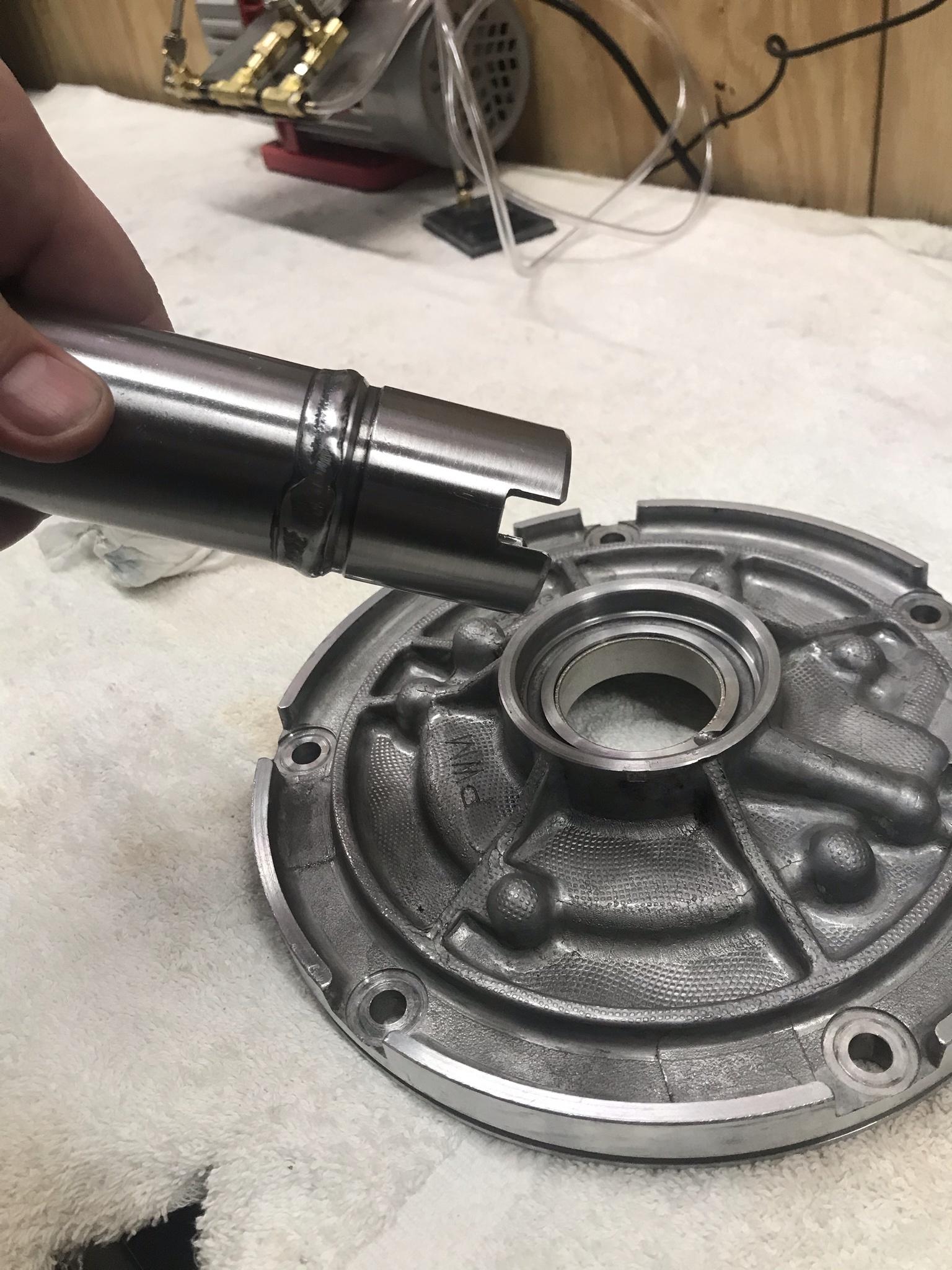
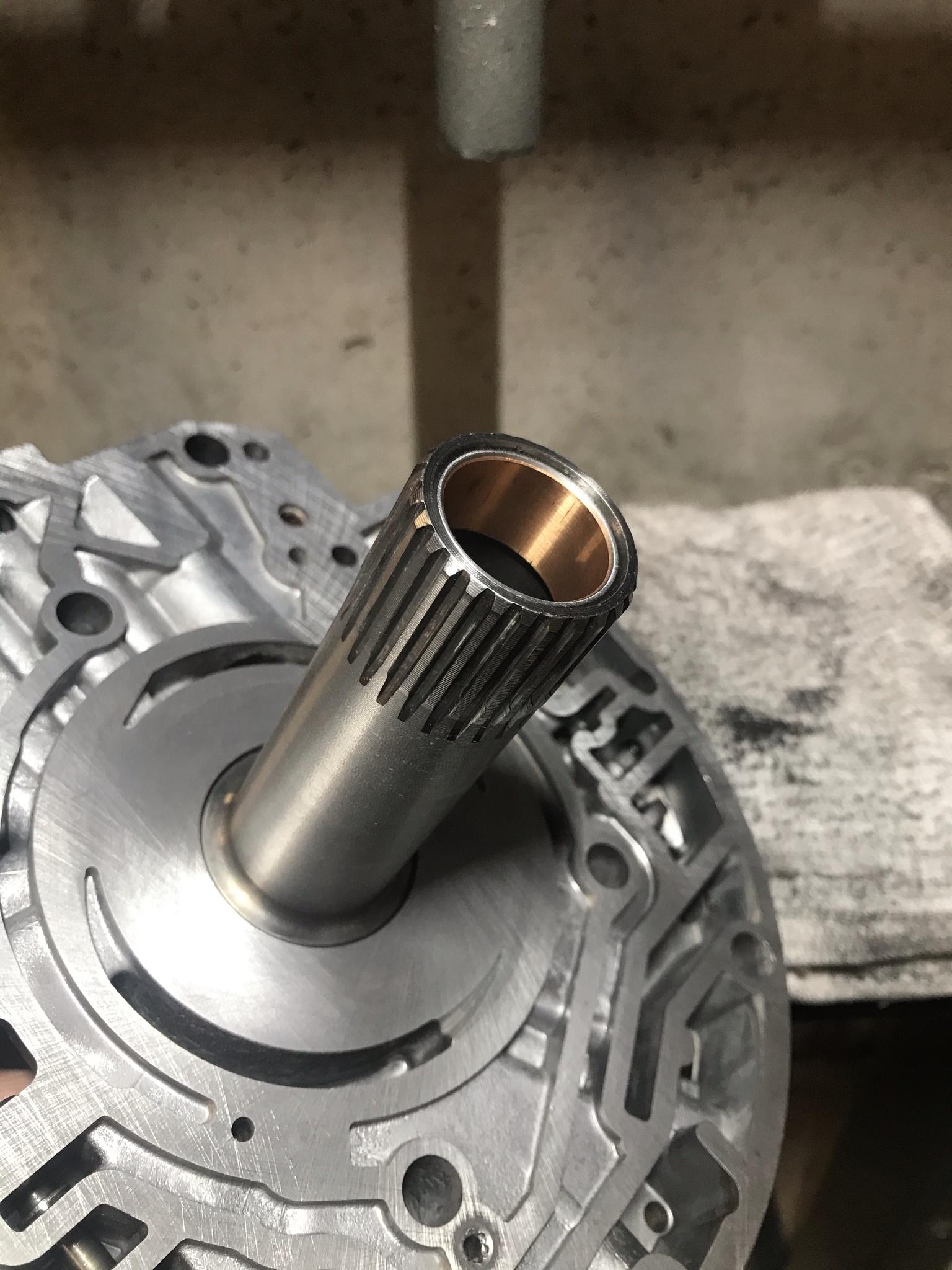
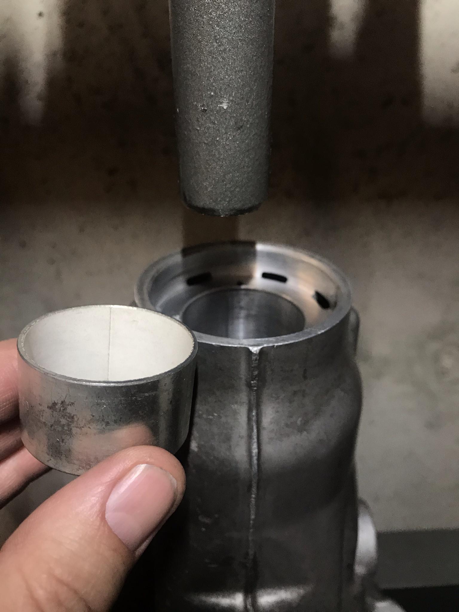
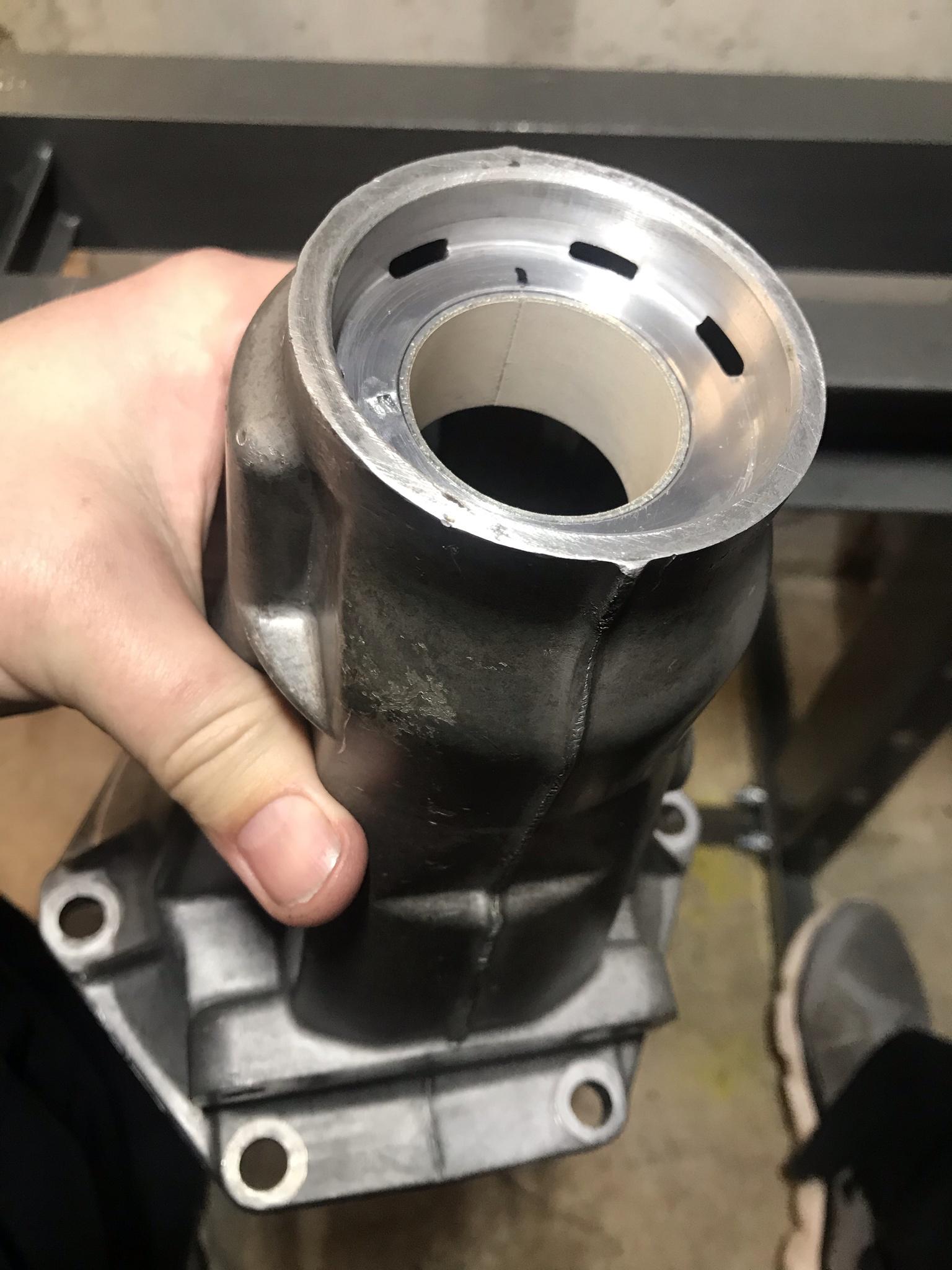
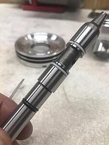
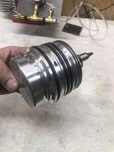
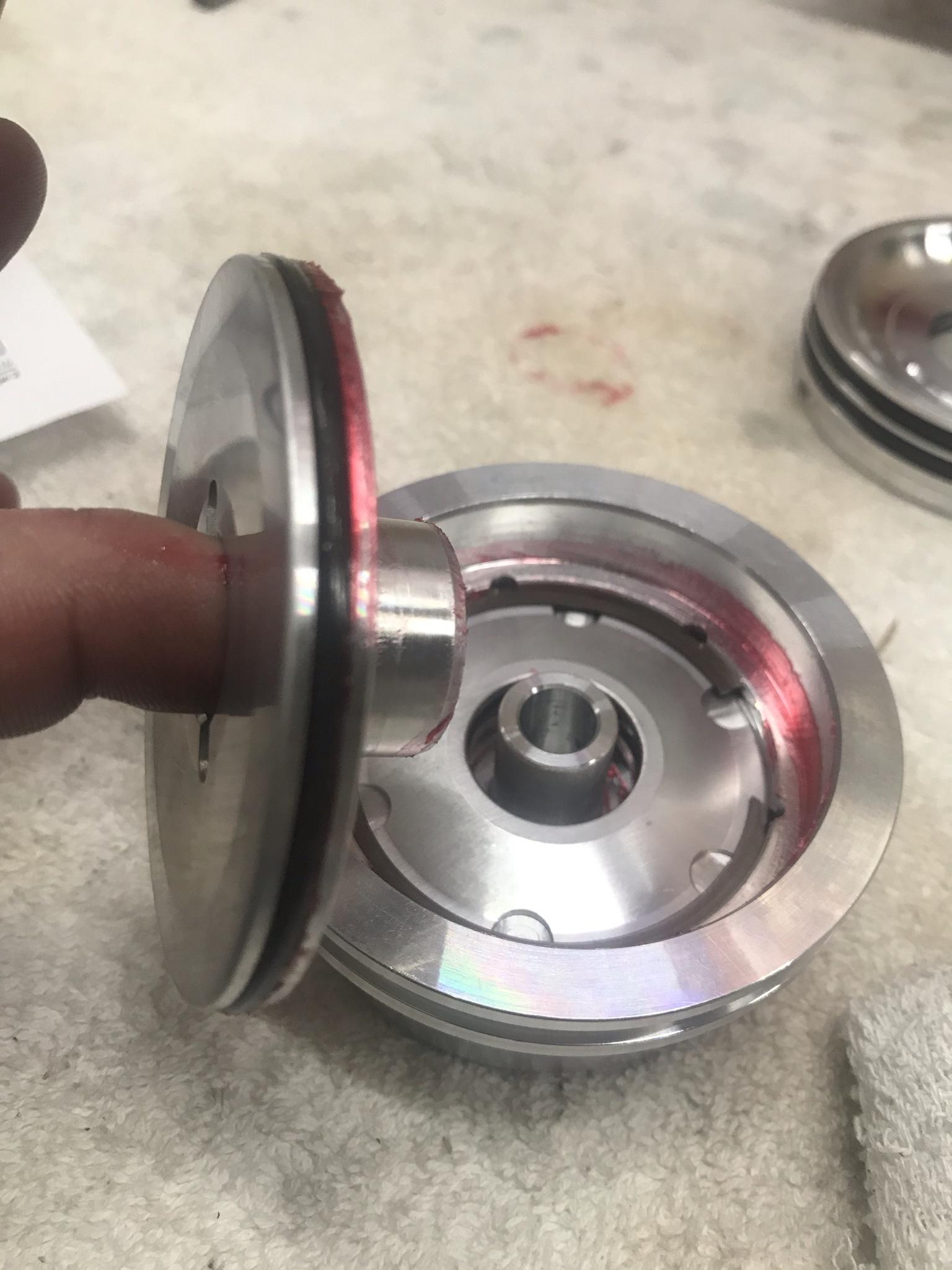
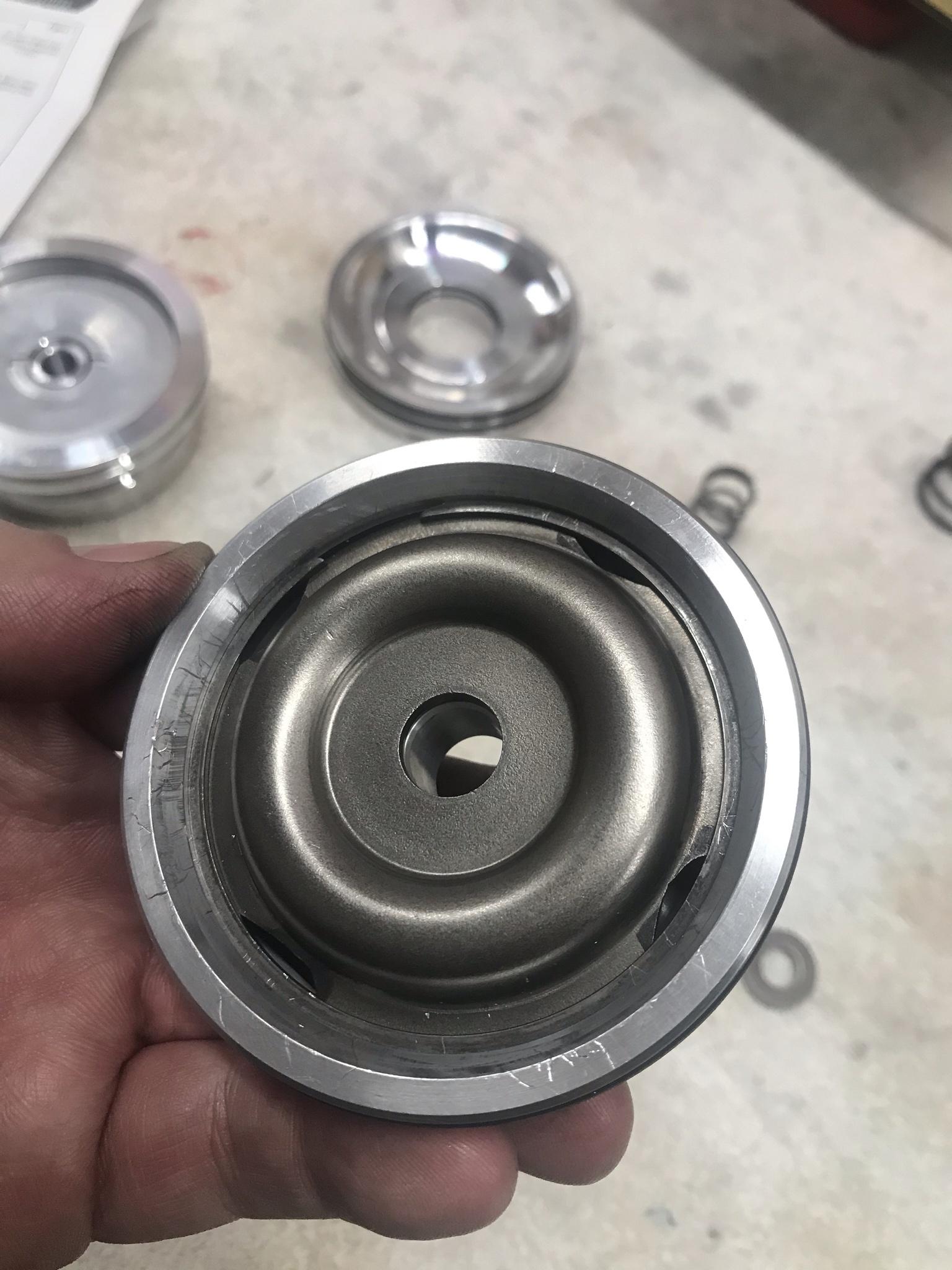
As I stated above, when I ordered the 4L79 drum setup from Mason I didnt plan to run a billet input shaft and he pressed in nice factory shaft for me along with the steel reinforcement collar. Between then and now I changed my mind and picked up the HD input shaft from Sonnax. But my question was since the reinforcement collar was already pressed on how does that now effect swapping shafts. Confirmed it wouldnt be an issue but not to make the exception the rule if possible. I had a junk input drum from another build I decided to play around with to get a feel of it coming out and back in before doing this on the 4L79 drum. I did take a little heat to the collar to warm it up and it popped right out. The same went for the 4L79 drum, it went out and back in very well. Im going to let it setup for a couple days after applying a liberal amount of green sleeve retainer then im going to air check the drum.

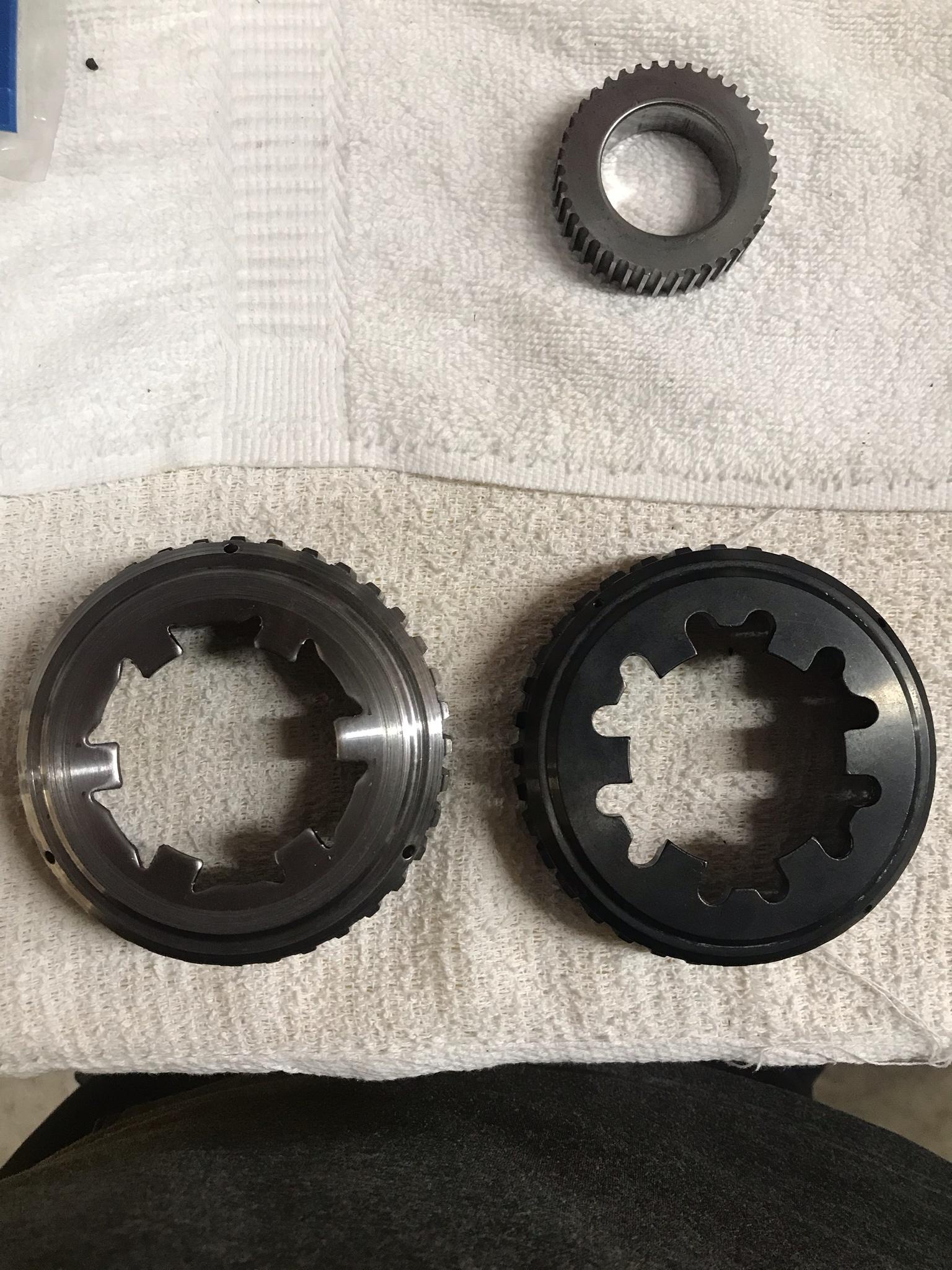
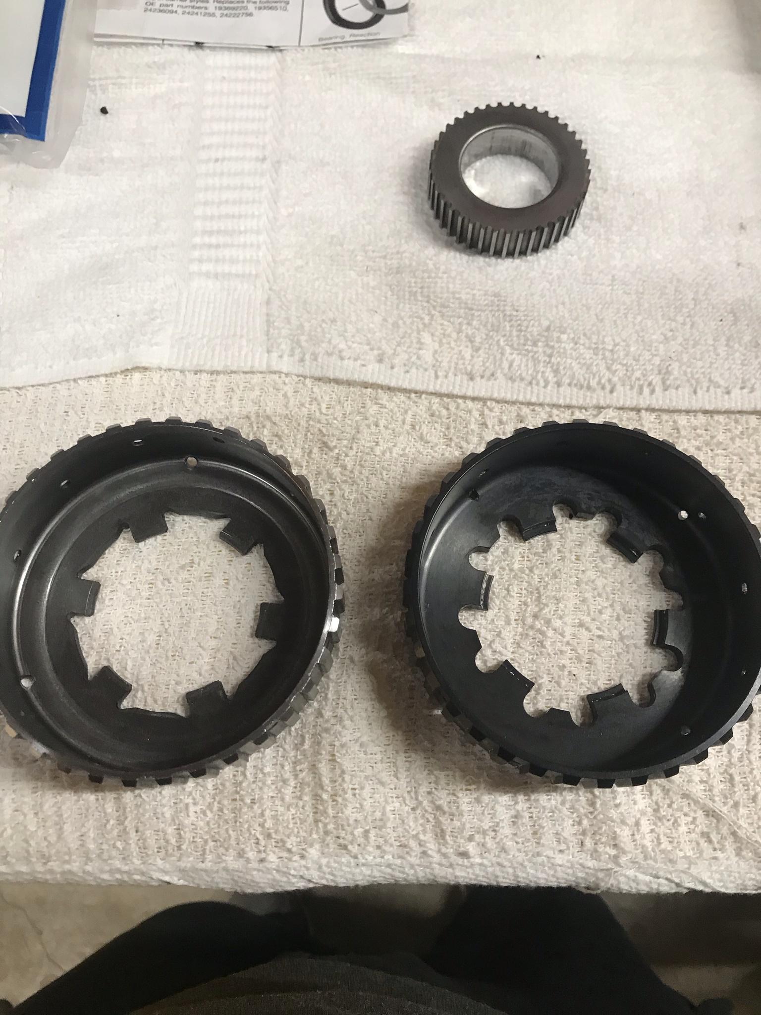
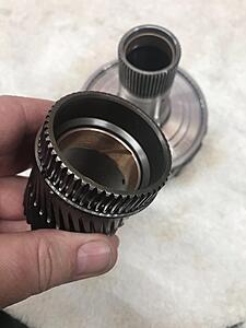
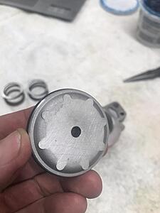
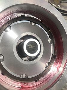
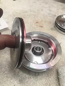
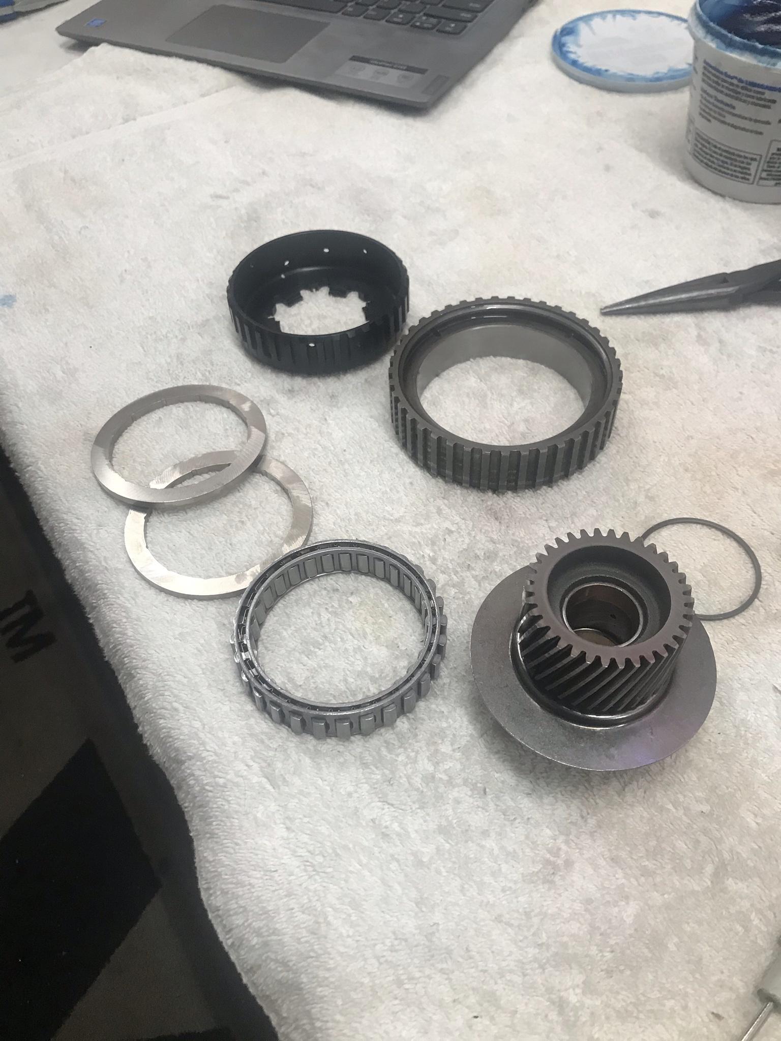
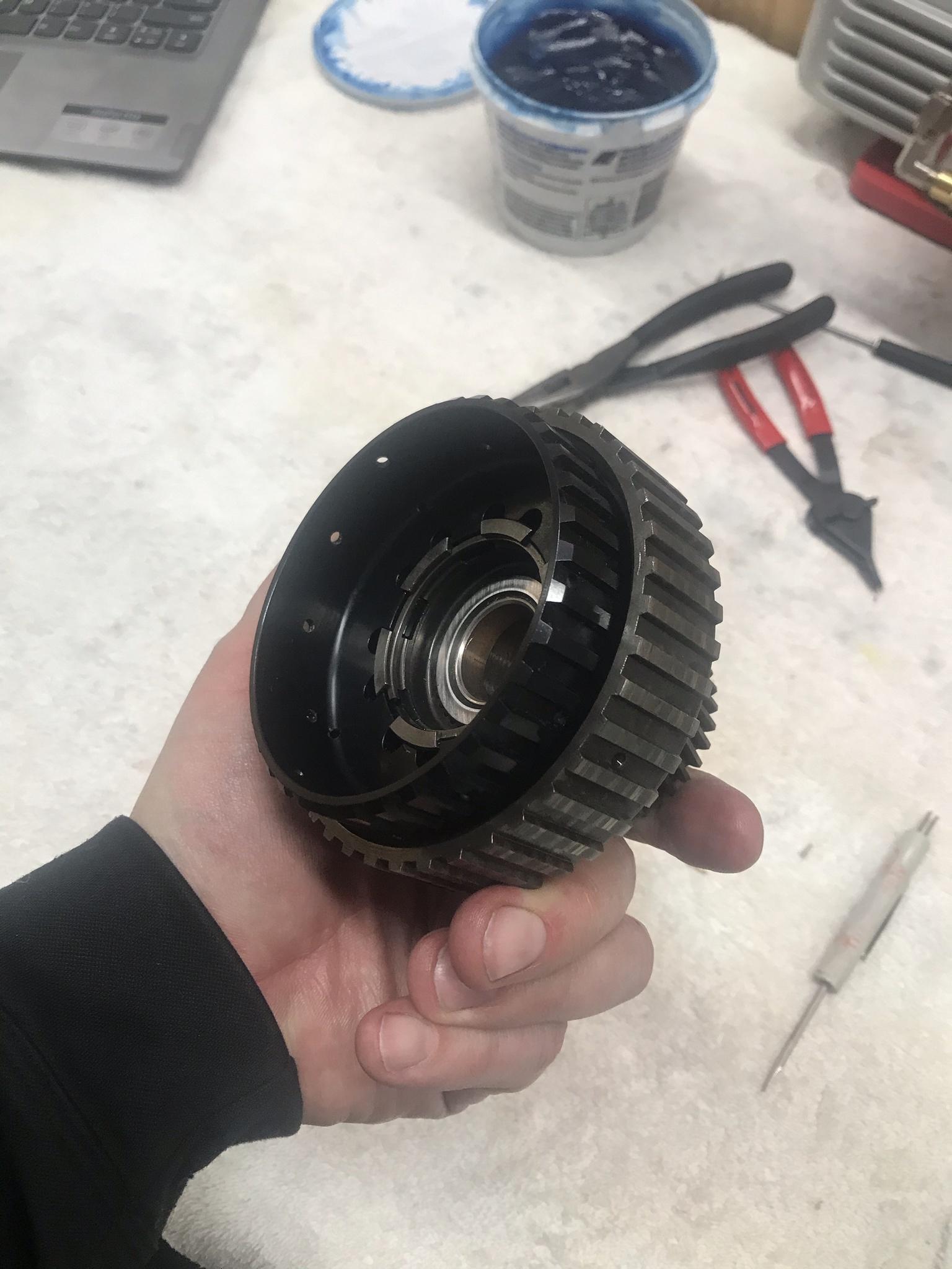
One piece im kind of stoked to run is the Sonnax 74574-HD clutch hub. I know this is another over kill piece for my application but I have broke a clutch hub before so this is just for my piece of mind I guess. Even though the factory clutch hub that is in the pictures isnt reusable due to scoring from the sprag cover but you can see the lugs on the clutch hub have notches in it already. Crazy how much more HD it is compared to the stock. Again, not for every build but im choosing to run one.


Once I get all my parts in I will list out my full parts list for this build. I dont have the valve body completely done yet as im waiting on a few parts. Once I get those and installed I will post my setup in there.
Its been the ***** getting parts!

Got the pump all ready to go. Actually vacuum tested it as well with all the factory internals before I took it apart to clean and prep. TCC apply, pressure reg, and boost valve were all at a minimum of 20" inhg. I planned to run the Sonnax 77805E-K TCC apply valve which has a PTFE seal to even further seal that bore as its a drop in valve but had a little issues getting the seal to form. Will work on that further. I will be running a TransGo .500 boost valve when it comes in. More on all that later. Here is the cleaned and prepped pump

As I stated above, when I ordered the 4L79 drum setup from Mason I didnt plan to run a billet input shaft and he pressed in nice factory shaft for me along with the steel reinforcement collar. Between then and now I changed my mind and picked up the HD input shaft from Sonnax. But my question was since the reinforcement collar was already pressed on how does that now effect swapping shafts. Confirmed it wouldnt be an issue but not to make the exception the rule if possible. I had a junk input drum from another build I decided to play around with to get a feel of it coming out and back in before doing this on the 4L79 drum. I did take a little heat to the collar to warm it up and it popped right out. The same went for the 4L79 drum, it went out and back in very well. Im going to let it setup for a couple days after applying a liberal amount of green sleeve retainer then im going to air check the drum.

One piece im kind of stoked to run is the Sonnax 74574-HD clutch hub. I know this is another over kill piece for my application but I have broke a clutch hub before so this is just for my piece of mind I guess. Even though the factory clutch hub that is in the pictures isnt reusable due to scoring from the sprag cover but you can see the lugs on the clutch hub have notches in it already. Crazy how much more HD it is compared to the stock. Again, not for every build but im choosing to run one.
Once I get all my parts in I will list out my full parts list for this build. I dont have the valve body completely done yet as im waiting on a few parts. Once I get those and installed I will post my setup in there.
Its been the ***** getting parts!
Last edited by 2BFAST; 02-08-2021 at 08:53 AM.
02-08-2021, 02:24 PM
#66
I have a little time so I will go ahead and list out the mods for this unit. I will break it down in sub assemblies
CASE:
Removed factory 3rd accumulator, install Superior K0136 directional switch valve
Block 4th accumulator with 5/16 set screw, remove piston and spring
Remove #6 checkball (overrun)
Remove low/reverse encapsulated check ball
24219937 2nd accumulator housing, aluminum 2nd accumulator piston with hardened pin, blue TransGo spring, piston, then orange TransGo spring (im told the orange springs have had a tendency to break?)
2-4 SERVO:
Sonnax 77911-03K 2nd servo
Sonnax 77767K 4th servo
Sonnax 77787-02K servo pin kit
TransGo blue 2nd cushion spring inside factory cushion spring
Modify factory steel 2nd apply cover
Alto extra wide carbon 2-4 band (will shoot for .60 band clearance on install)
VALVE BODY:
4209354 Valve body
3-2 control valve blocked inboard
3-2 downshift valve blocked inboard
Central valve bodies .001" oversized AFL valve
TransGo white AFL spring inside factory AFL spring
TransGo yellow low overrun spring
TransGo white 1-2 accumulator spring
TransGo 1-2 shift valve and spacer
Sonnax 77754-41 HD 2-3 shift valve
Sonnax 77754-35K forward & reverse abuse valve kits
Sonnax 77964-08K o-ringed end plugs
Sonnax 77754-03K TCC regulator & isolator kit
(I have vacuumed tested most of the valve body but im waiting on a couple parts to complete. Its looking really good so far. Will post results when this is complete)
TransGo seperator plate w/ steel reinforcement corner plate
Orifices drilled to:
Band release - .104"
Rev input - .104"
3-4 clutch and 3-4 clutch signal - .110"
1-2 shift - .096"
2-3 shift - .140"
3-4 shift - .110"
Low/reverse - .093
Forward clutch - .086"
AFL factory size
Borg Warner EPC solenoid (early style)
Rostra wiring harness (early style)
Sonnax 77980-01K wiring harness connector retainer
Rostra pressure switch manifold
TransGo torlon check *****, serpator plate peened to except check *****
AC Delco A & B shift solenoids
Rostra TCC PWM solenoid
Rostra 3-2 Shift solenoid
Aluminum forward accumulator piston with hardened pin
PUMP:
2420661 pump
Re-seat pressure relief ball
Wide bronze inner and outer stator bushings
10 vane rotor
13 vane slide w/ new pin
TransGo hardened retaining rings
TransGo high RPM priming spring
TransGo .500 boost valve
TransGo orange bumper and orange main regulator springs
Sonnax 77805E-K TCC o-ringed apply valve kit
(I have also vacuum tested most of the pump but waiting on a couple parts to complete the testing. Like the VB, looking good so far. Will post results when assmebled)
LOWER UNIT OF CASE:
Factory lower 5 pinion carrier
Borg warner HD low/reverse roller clutch (late design)
Borg Warner low/reverse clutches
Raybestos "turbulator" steels
Sonnax 74678L-HD billet output shaft 2WD
UPPER UNIT OF CASE:
GM factory 5 pinion upper carrier
Sonnax 77010-01 wide sun gear bushing
Sonnax 77749-02K smart shell
Sonnax 74602-01K HD reaction shaft kit
INPUT DRUM:
4L79 custom factory input drum
Sonnax 77733-11S billet input shaft (non reluctor 300MM)
Sonnax 77733-51K reinforcement sleeve kit with billet overrun piston
Seal aftermarket product Hi-per blue molded 3-4 and forward pistons
TransGo 7CS hi-rev forward and 3-4 springs
Borg Warner overrun clutches
AC Delco overrun steels
Borg Warner forward clutches
Raybestos forward steels
4L79 custom 3-4 apply plate .180"
8 Raybestos custom wide 3-4 clutches .062"
8 4L79 custom wide 3-4 steels .072"
5 4L79 custom load release springs
Sonnax 74574-HD sprag clutch hub
Borg Warner 29 element dual cage forward sprag
REVERSE INPUT DRUM:
AC Delco reverse input drum
Borg Warner clutches
Raybestos "turbulator " steels
Alto lower wave plate (replaces belleville plate)
Replace outer bushing to except roller bearing to replace plastic thrust washer
Pictures to come!
Last edited by 2BFAST; 01-06-2022 at 07:48 AM.
The following users liked this post:
n2xlr8n66 (06-30-2021)
02-08-2021, 02:55 PM
#67
TECH Junkie
#6 checkball.
not #4
not #4
The following users liked this post:
2BFAST (02-08-2021)
The following users liked this post:
2001 5.3 formula (08-02-2024)
02-09-2021, 11:00 AM
#69
Had a little time last night and got a few things knocked out.
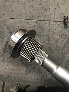
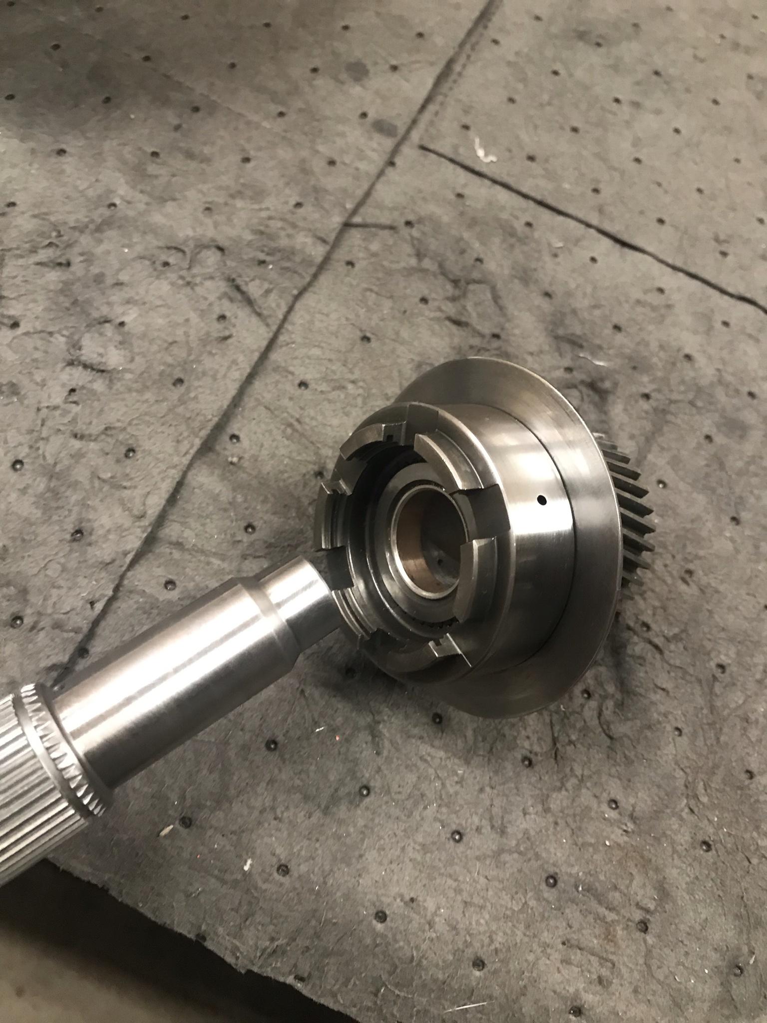
Upper sun gear bushings installed and fitted to the output shaft. Hit the end of the output shaft with scotchbrite. Fits well

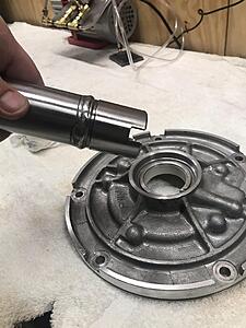
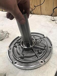
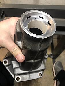
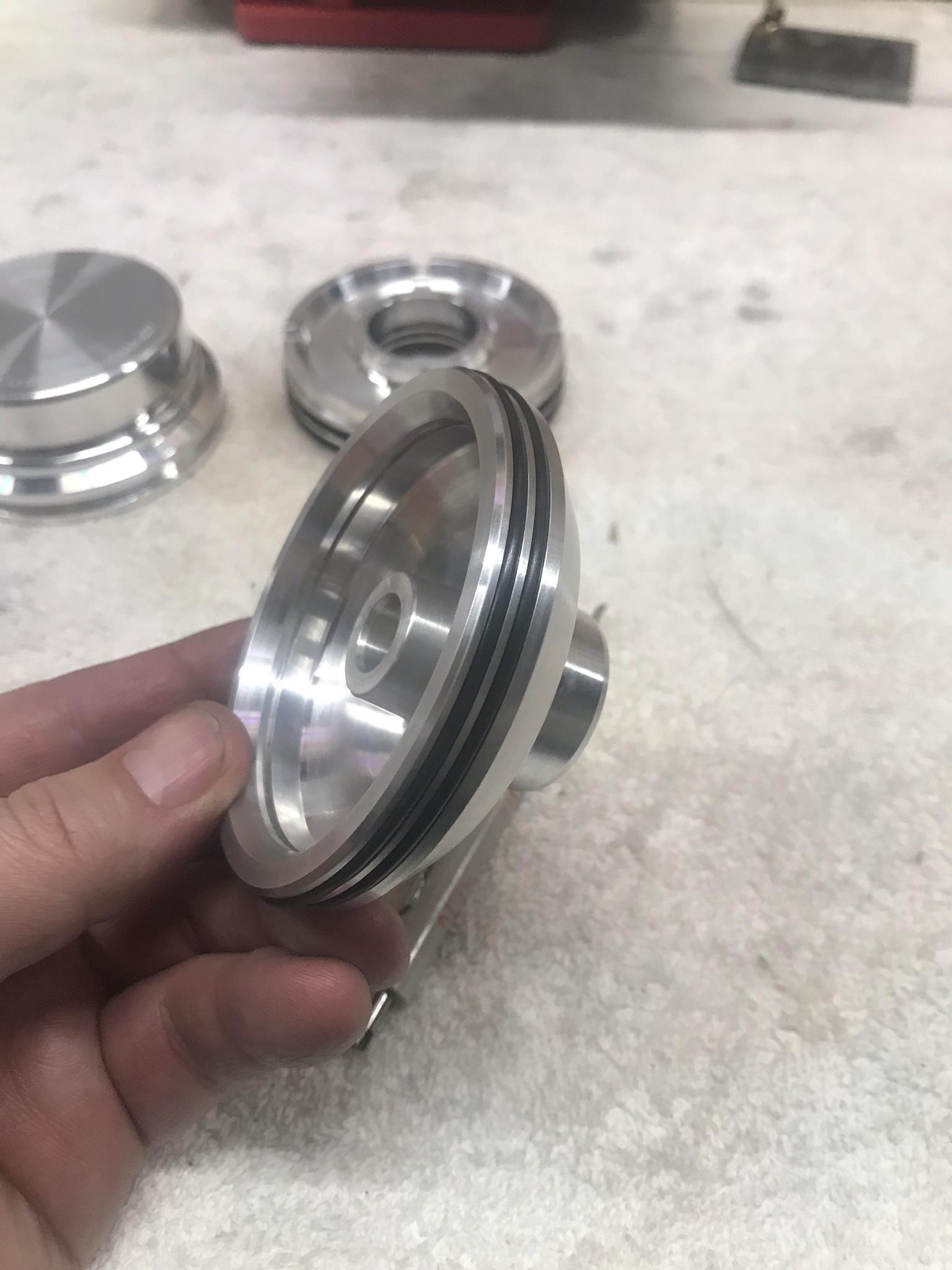
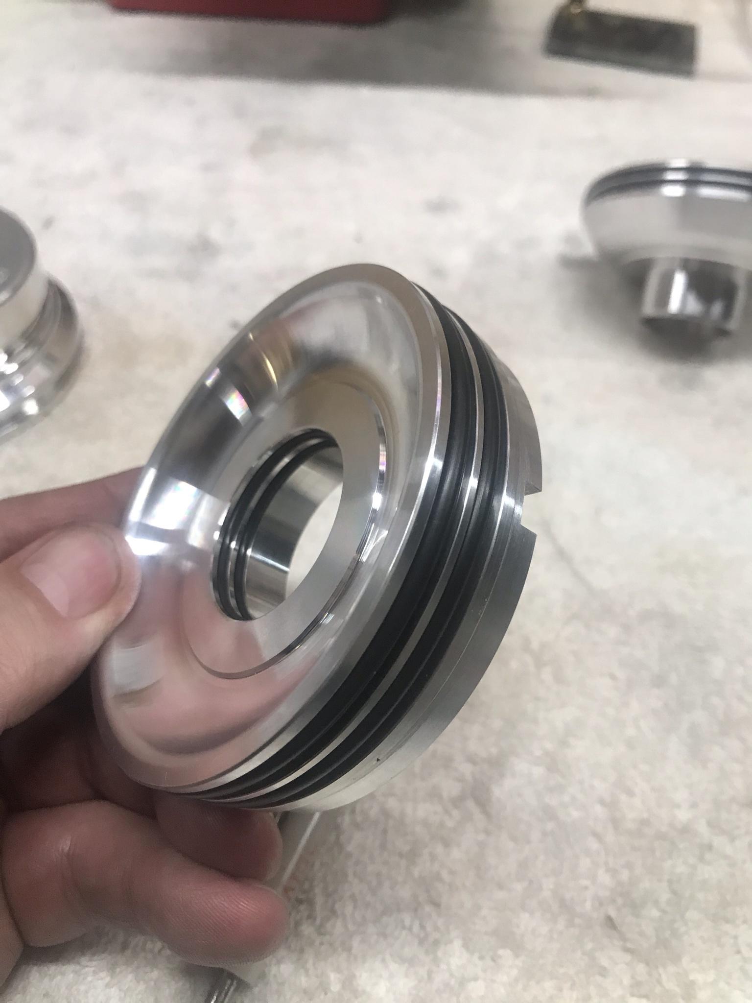
Pump cover bushing next. You can see there is a ledge at the bottom. Dont press it past this

Also the joint where the bushing comes together goes on top. More of the wear will be at the bottom of the bushing and this prevents the bushing from possibly splitting.

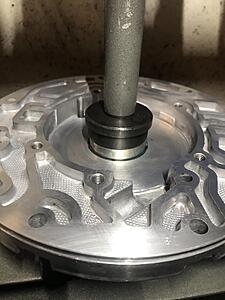
Using a converter hub to test fit the bushing to make sure everything will fit. Fits very nice
Upper and lower wide Sonnax stator bushings installed with green seal retainer
Fitted the stator half on the input shaft and it fits very well and smooth
Sonnax wide sun gear bushing installed in the lower sun gear
Fitted on the lower reaction tube. Sometimes you need to tap on the side with a soft hammer or dead blow and rotate the part around to fit the bushing. After a few taps while rotating it now fits well.
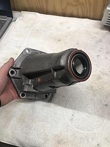
Went ahead and pressed in the tailshaft bushing. Again you can see the seam of the bushing goes up. Also tapped in the new seal and got all that out of the way

More to come as parts come in!
Upper sun gear bushings installed and fitted to the output shaft. Hit the end of the output shaft with scotchbrite. Fits well

Pump cover bushing next. You can see there is a ledge at the bottom. Dont press it past this
Also the joint where the bushing comes together goes on top. More of the wear will be at the bottom of the bushing and this prevents the bushing from possibly splitting.

Using a converter hub to test fit the bushing to make sure everything will fit. Fits very nice

Upper and lower wide Sonnax stator bushings installed with green seal retainer

Fitted the stator half on the input shaft and it fits very well and smooth

Sonnax wide sun gear bushing installed in the lower sun gear

Fitted on the lower reaction tube. Sometimes you need to tap on the side with a soft hammer or dead blow and rotate the part around to fit the bushing. After a few taps while rotating it now fits well.

Went ahead and pressed in the tailshaft bushing. Again you can see the seam of the bushing goes up. Also tapped in the new seal and got all that out of the way

More to come as parts come in!
02-09-2021, 06:40 PM
#70
TECH Addict

Here is some info that PBA/Dana has shared in the past on how to prep the races of the forward sprag . "The inner race must have no wear and must be perfectly flat and have a "mirror" finish. The outer race should be flat and rough, use 36 grit and sand it in the direction of rotation by rolling it across a wooden bench and do it about 15 - 20 times. Rinse with solvent and blow it off with high pressure air, same for the inner race."
02-09-2021, 08:25 PM
#71
TECH Junkie
I would actually recommend that the outer race not be left that rough...
You can sand it rough if you need to, but i would smooth it out closer to how you finish the inner race.
I had discussed this with Dana a while back...
Since I told him about this, I believe that he no longer leaves the outer race that rough anymore.
I had told a few different builders about this, and I believe everybody was on board.
If you are using one of the Borg-Warner sprags that use the "Bronze Colored" end-caps...
The rear end-cap should be modified, by drilling 4 or 5 lube holes in it.
Make sure that the end-cap is still perfectly flat after drilling.
The end-caps are not a similar type of bronze alloy that would be found for the bushings of the transmission.
The end-caps are made of a much harder Bronze alloy that contains Iron, Aluminum, and a higher Tin content...
Making the end-caps very hard.
They are hard enough that the steel overrun hub below the rear end-cap will become worn from the sprag rotating.
The holes drilled are to improve lubrication between the rear end-cap and the steel overrun hub.
Dana first mentioned this to me, and I perform this modification in all units now.
02-09-2021, 08:34 PM
#72
TECH Junkie
Also be careful when using a Sonnax wide Sun-Gear bushing...
Fitment with this bushing is often poor.
Extra care should be taken to make sure that Sun-Gear will rotate smoothly on the Reaction-Shaft after the bushing has been installed (rotate the Sun-Gear while sliding it up/ down the Reaction-Shaft).
If the Sun-Gear gets stuck or difficult to turn... you will have to increase the clearance.
Honing this bushing/ correcting clearance is often needed.
Dana has mentioned that aftermarket Sun-Gears are far more problematic in terms of fitment for this bushing.
An alternative, would be to install 2 OEM bushings into the Sun-Gear.
This makes for an even wider bushing area than the Sonnax bushing...
And more importantly fits better.
This is my preference, when building these transmissions.
02-10-2021, 07:24 AM
#73
TECH Junkie
I also install a 2nd stock bushing rather than the sonnax wide
if doing this on a 700r4, you'll interfere with the chamfur of the reaction tube, and you'll need to spend a couple minutes in the lathe to move the chamfur
if doing this on a 700r4, you'll interfere with the chamfur of the reaction tube, and you'll need to spend a couple minutes in the lathe to move the chamfur
02-10-2021, 07:50 AM
#74
Here is some info that PBA/Dana has shared in the past on how to prep the races of the forward sprag . "The inner race must have no wear and must be perfectly flat and have a "mirror" finish. The outer race should be flat and rough, use 36 grit and sand it in the direction of rotation by rolling it across a wooden bench and do it about 15 - 20 times. Rinse with solvent and blow it off with high pressure air, same for the inner race."
I would actually recommend that the outer race not be left that rough...
You can sand it rough if you need to, but i would smooth it out closer to how you finish the inner race.
I had discussed this with Dana a while back...
Since I told him about this, I believe that he no longer leaves the outer race that rough anymore.
I had told a few different builders about this, and I believe everybody was on board.
If you are using one of the Borg-Warner sprags that use the "Bronze Colored" end-caps...
The rear end-cap should be modified, by drilling 4 or 5 lube holes in it.
Make sure that the end-cap is still perfectly flat after drilling.
The end-caps are not a similar type of bronze alloy that would be found for the bushings of the transmission.
The end-caps are made of a much harder Bronze alloy that contains Iron, Aluminum, and a higher Tin content...
Making the end-caps very hard.
They are hard enough that the steel overrun hub below the rear end-cap will become worn from the sprag rotating.
The holes drilled are to improve lubrication between the rear end-cap and the steel overrun hub.
Dana first mentioned this to me, and I perform this modification in all units now.
You can sand it rough if you need to, but i would smooth it out closer to how you finish the inner race.
I had discussed this with Dana a while back...
Since I told him about this, I believe that he no longer leaves the outer race that rough anymore.
I had told a few different builders about this, and I believe everybody was on board.
If you are using one of the Borg-Warner sprags that use the "Bronze Colored" end-caps...
The rear end-cap should be modified, by drilling 4 or 5 lube holes in it.
Make sure that the end-cap is still perfectly flat after drilling.
The end-caps are not a similar type of bronze alloy that would be found for the bushings of the transmission.
The end-caps are made of a much harder Bronze alloy that contains Iron, Aluminum, and a higher Tin content...
Making the end-caps very hard.
They are hard enough that the steel overrun hub below the rear end-cap will become worn from the sprag rotating.
The holes drilled are to improve lubrication between the rear end-cap and the steel overrun hub.
Dana first mentioned this to me, and I perform this modification in all units now.
Also be careful when using a Sonnax wide Sun-Gear bushing...
Fitment with this bushing is often poor.
Extra care should be taken to make sure that Sun-Gear will rotate smoothly on the Reaction-Shaft after the bushing has been installed (rotate the Sun-Gear while sliding it up/ down the Reaction-Shaft).
If the Sun-Gear gets stuck or difficult to turn... you will have to increase the clearance.
Honing this bushing/ correcting clearance is often needed.
Dana has mentioned that aftermarket Sun-Gears are far more problematic in terms of fitment for this bushing.
An alternative, would be to install 2 OEM bushings into the Sun-Gear.
This makes for an even wider bushing area than the Sonnax bushing...
And more importantly fits better.
This is my preference, when building these transmissions.
Fitment with this bushing is often poor.
Extra care should be taken to make sure that Sun-Gear will rotate smoothly on the Reaction-Shaft after the bushing has been installed (rotate the Sun-Gear while sliding it up/ down the Reaction-Shaft).
If the Sun-Gear gets stuck or difficult to turn... you will have to increase the clearance.
Honing this bushing/ correcting clearance is often needed.
Dana has mentioned that aftermarket Sun-Gears are far more problematic in terms of fitment for this bushing.
An alternative, would be to install 2 OEM bushings into the Sun-Gear.
This makes for an even wider bushing area than the Sonnax bushing...
And more importantly fits better.
This is my preference, when building these transmissions.
02-10-2021, 08:22 AM
#75
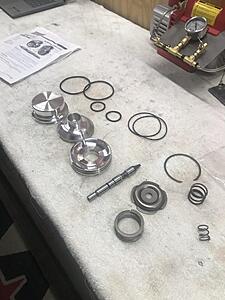
The rest of the parts showed up yesterday so I got everything out, organized, and started to assemble sub assemblies. Im only waiting on one part for the valve body which should be here today. Once I get that and installed, ill finish my vacuum testing and post the results.
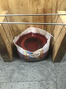
Got all the frictions soaking
Got the rest of the pump stator half together. When I finish vacuum testing the valve body ill post the results of the pump stator half also
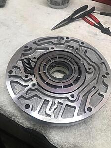
Lets start with the other half of the pump. I did run a straight edge over the surface with the rotor in and also slide to make sure all was flat and it was

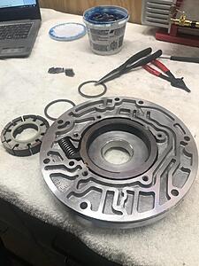
Dumped some fluid over the assembly and all rotates free.
Low/Roller HD sprag and Sonnax inner race
If anyone is curious about the Sonnax Smartshell here is a close up of the different inner race compared to the factory.
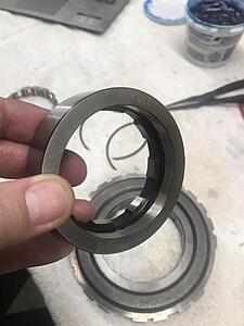
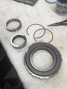
Forward sprag. Again, I checked for chatter marks, grooving, ect on the inner and outer races and all were smooth. I lightly buffed the surfaces with scotchbrite and assembled with a little ATF


2nd accumulator housing with modified piston and new hardened pin. Hit is also with a little scotchbrite. TransGo blue spring, then piston, then orange spring. This allows for smooth part throttle shifts and firm and quick WOT shifts


Servos are next. I can say, there are seals and o-rings all over this setup! Pretty impressive


Got all the frictions soaking
Got the rest of the pump stator half together. When I finish vacuum testing the valve body ill post the results of the pump stator half also

Lets start with the other half of the pump. I did run a straight edge over the surface with the rotor in and also slide to make sure all was flat and it was


Dumped some fluid over the assembly and all rotates free.

Low/Roller HD sprag and Sonnax inner race

If anyone is curious about the Sonnax Smartshell here is a close up of the different inner race compared to the factory.

Forward sprag. Again, I checked for chatter marks, grooving, ect on the inner and outer races and all were smooth. I lightly buffed the surfaces with scotchbrite and assembled with a little ATF
2nd accumulator housing with modified piston and new hardened pin. Hit is also with a little scotchbrite. TransGo blue spring, then piston, then orange spring. This allows for smooth part throttle shifts and firm and quick WOT shifts


Servos are next. I can say, there are seals and o-rings all over this setup! Pretty impressive


 02-10-2021, 08:33 AM
#76
TECH Addict
I would actually recommend that the outer race not be left that rough...
You can sand it rough if you need to, but i would smooth it out closer to how you finish the inner race.
I had discussed this with Dana a while back...
Since I told him about this, I believe that he no longer leaves the outer race that rough anymore.
I had told a few different builders about this, and I believe everybody was on board.
02-10-2021, 09:23 PM
#77
My elusive Sonnax forward abuse valve finally showed up which was the last piece to the valve body before completing final vacuum testing. Here are my results all in "in-hg" with the modifications listed a few posts back:
3-4 Shift Valve:
Upper - 21"
Lower - 21"
Reverse Abuse Bore Plug:
22"
3-2 Control Valve:
Upper - 24"
Lower - 24"
Reverse Abuse Valve:
22"
Forward Abuse Valve:
Upper - I cant ever get this to vacuum test, I stroke the manual valve and I cant ever get a reading here
Lower - 22"
Forward Abuse Plug:
21"
Low Overrun Valve:
22"
1-2 Shift Valve:
Upper - 23"
Lower - 20"
2-3 Shift & 2-3 Shuttle Valves:
Upper - 24"
Middle - 20"
Lower - 19"
Accumulator Valve & Sleeve:
20"
Actuator Feel Limit Valve:
20"
TCC Regulator Valve:
Upper - 25"
Lower - 17"
End Plugs:
20"
4-3 Sequence Valve & 3-4 Relay Valve:
Upper - 20"
Middle 1 - 21"
Middle 2 - 20"
Lower - 20"
Here are the results of the pump stator half with the modifications above a few posts back:
TCC Apply Valve:
Upper - 19"
Lower - Another one I cant ever seem to get a good reading
Boost Valve Assembly:
17"
Pressure Regulator Valve:
23"
As you can see things are looking pretty tight and sealed as far as I can see. Im pretty excited about that
Last edited by 2BFAST; 02-10-2021 at 09:31 PM.
The following users liked this post:
n2xlr8n66 (06-30-2021)
02-11-2021, 02:06 PM
#79
TECH Junkie
Which feed holes?
In the separator plate...its just because burrs suck after drilling and can ruin a gasket
Feed holes in a shaft should have a slight chamfur to reduce any sharp edge for stress
It also can help with oil flow
In sealing ring areas, its so there's minimal chance anything gets cut or torn during install
02-11-2021, 03:40 PM
#80
Which feed holes?
In the separator plate...its just because burrs suck after drilling and can ruin a gasket
Feed holes in a shaft should have a slight chamfur to reduce any sharp edge for stress
It also can help with oil flow
In sealing ring areas, its so there's minimal chance anything gets cut or torn during install
In the separator plate...its just because burrs suck after drilling and can ruin a gasket
Feed holes in a shaft should have a slight chamfur to reduce any sharp edge for stress
It also can help with oil flow
In sealing ring areas, its so there's minimal chance anything gets cut or torn during install