
'70 Nova LY6/TH400 6.0VVT


 10-31-2012, 09:55 PM
#582

I celebrate life every day!
FYI, my L92 heads measured at a touch over 70 cc's. I had them shaved to 66 to get 10.45:1 or so CR. Which Wisecos did you buy again? I see they offer different compression heights.
11-01-2012, 10:03 AM
#583
The pistons are Wiseco K398X3. They have a 3.2cc valve relief and 1.304 compression height.
Here is my calculation, not using the measured piston stick-out since I'm not sure on the measurement yet:
bore 4.03
stroke 3.622
rod length 6.125
comp ht 1.304
deck height 9.224
piston protrusion (calc) 0.016
gasket 0.051 in
quench 0.035 in
quench 7.316 cc
head 70 cc
valve relief 3.2 cc
displacement 757.1 cc
SCR 10.40
stroke 3.622
rod length 6.125
comp ht 1.304
deck height 9.224
piston protrusion (calc) 0.016
gasket 0.051 in
quench 0.035 in
quench 7.316 cc
head 70 cc
valve relief 3.2 cc
displacement 757.1 cc
SCR 10.40
11-01-2012, 10:55 AM
#584
Piston valve clearance, clay method, VVT
Here is the clay method I used for checking PTV clearance using a VVT cam. It isn't all that different from doing it with a nonVVT cam, just a few added steps and for now the use of a sacrificed phaser.
First I locked the phaser to full advance as shown below. I am using a cut-off screw that happened to fit well when combined with a phaser limiter block.

Next, I installed the cam using the dot-to-dot method.

Then I applied approximately 1/4" thick strips of modelling clay to the top of the piston with the piston dry & clean. I pressed them into place so they stuck well to the piston, then sprayed the top of the clay, the valves, and the combustion chamber with WD-40 to prevent sticking.

Next (not shown) I installed two solid lifters for this bore. Then I installed the cylinder head with an old gasket of the same installed thickness as the gasket I intend to use (in this case, the same PN MLS gasket from GM).
I installed my old (nonadjustable) pushrods and rockers, then adjusted them to zero lash using the rocker bolts . Before this can be done the crank must be rotated 180 because when the timing marks are set dot-to-dot, the no1 cylinder is in the overlap phase (both valves partially open).
Finally, I rotated the crank through two revolutions so the valves would make an impression on the clay. The impression left would represent minimum clearance with the cam at full advance, but I care about both full advance and full retard.
I rotated until both the crank sprocket dot and cam sprocket "dot" (arrow) were facing up. This put the no1 valves on their base circle. I made a mark to the cam sprocket tooth nearest the crank dot so I could get it back into position later.

Next I removed the phaser and locked it to full retard as shown below. In this case, I cut off the tip of a 1/4" hex drive philips bit which happened to fit perfectly.

Then I reinstalled the phaser. To do this, I first put the phaser on the nose of the cam without the timing chain installed. This allowed me to rotate the cam by hand to the new retarded position and line up the mark I made on the sprocket. Then I installed the chain and rotated the crank two revolutions.
The resulting impressions in the clay should represent the minimum clearance for both full advance & full retard. I only had to install the heads once - I just had to adjust the cam phasing to get both extremes. Pardon the dirty marks in the clay - the heads still need a bit more cleaning.

Next I used an Exacto knife to slowly and carefully slice through the clay. This gave me a nice cross section. Here is the intake:

And here is the exhaust:

After a search through my boxes, I couldn't find my trusty calipers (!) so I used a steel rule instead. Axial thickness seemed to agree with what I measured before. The advantage of this method over the indicator method is I can also observe radial valve clearance, which I think looks pretty good. The radial clearance was about 3/16" for both valves. Hopefully I can find my calipers and get a better measurement tonight - they seem to have walked off over the last week.
Here is the clay method I used for checking PTV clearance using a VVT cam. It isn't all that different from doing it with a nonVVT cam, just a few added steps and for now the use of a sacrificed phaser.
First I locked the phaser to full advance as shown below. I am using a cut-off screw that happened to fit well when combined with a phaser limiter block.
Next, I installed the cam using the dot-to-dot method.
Then I applied approximately 1/4" thick strips of modelling clay to the top of the piston with the piston dry & clean. I pressed them into place so they stuck well to the piston, then sprayed the top of the clay, the valves, and the combustion chamber with WD-40 to prevent sticking.
Next (not shown) I installed two solid lifters for this bore. Then I installed the cylinder head with an old gasket of the same installed thickness as the gasket I intend to use (in this case, the same PN MLS gasket from GM).
I installed my old (nonadjustable) pushrods and rockers, then adjusted them to zero lash using the rocker bolts . Before this can be done the crank must be rotated 180 because when the timing marks are set dot-to-dot, the no1 cylinder is in the overlap phase (both valves partially open).
Finally, I rotated the crank through two revolutions so the valves would make an impression on the clay. The impression left would represent minimum clearance with the cam at full advance, but I care about both full advance and full retard.
I rotated until both the crank sprocket dot and cam sprocket "dot" (arrow) were facing up. This put the no1 valves on their base circle. I made a mark to the cam sprocket tooth nearest the crank dot so I could get it back into position later.
Next I removed the phaser and locked it to full retard as shown below. In this case, I cut off the tip of a 1/4" hex drive philips bit which happened to fit perfectly.
Then I reinstalled the phaser. To do this, I first put the phaser on the nose of the cam without the timing chain installed. This allowed me to rotate the cam by hand to the new retarded position and line up the mark I made on the sprocket. Then I installed the chain and rotated the crank two revolutions.
The resulting impressions in the clay should represent the minimum clearance for both full advance & full retard. I only had to install the heads once - I just had to adjust the cam phasing to get both extremes. Pardon the dirty marks in the clay - the heads still need a bit more cleaning.
Next I used an Exacto knife to slowly and carefully slice through the clay. This gave me a nice cross section. Here is the intake:
And here is the exhaust:
After a search through my boxes, I couldn't find my trusty calipers (!) so I used a steel rule instead. Axial thickness seemed to agree with what I measured before. The advantage of this method over the indicator method is I can also observe radial valve clearance, which I think looks pretty good. The radial clearance was about 3/16" for both valves. Hopefully I can find my calipers and get a better measurement tonight - they seem to have walked off over the last week.
 11-05-2012, 02:25 PM
#588
Well I was going to get some stuff done this weekend, but I came out to the river Nile running through my garage, under the Nova and out into the street. My water heater sprung a leak at an inlet fitting. It had one of those flexible stainless braided hoses and it was shooting water from the crimp area. Thankfully the flood missed anything important, but it still took up most of my day between moving things around and replacing the pipes. As I dried stuff I couldn't help but think about all the people affected by the hurricane. I was looking at some of my best memories captured in photos and boxed up for storage, photos that certainly would have been lost in a real flood. My heart goes out to everyone suffering through the effects of that storm. Hope everyone there is doing okay.
Tomorrow I am dropping my heads off with Tod McKenzie at his shop (McKenzie's Racing) in Oxnard. I was going to clean and assemble them myself, but I'm paranoid about cleaning aluminum now and even if I wasn't I think it's worth a few bucks to have them hot tanked and blasted. After searching around with no luck for a rental/loaner spring compressor that could handle the dual springs, I've decided to also have him assemble the heads. That'll save time and get me going a little sooner. Total $80. Does that seem reasonable to clean & assemble heads?
I found my calipers while I was moving stuff and did a quick check on this. It is so hard to measure clay, but I was getting around .040. Should be okay.
Thanks man! Still can't thank you enough for that pedal.
Tomorrow I am dropping my heads off with Tod McKenzie at his shop (McKenzie's Racing) in Oxnard. I was going to clean and assemble them myself, but I'm paranoid about cleaning aluminum now and even if I wasn't I think it's worth a few bucks to have them hot tanked and blasted. After searching around with no luck for a rental/loaner spring compressor that could handle the dual springs, I've decided to also have him assemble the heads. That'll save time and get me going a little sooner. Total $80. Does that seem reasonable to clean & assemble heads?
Thanks man! Still can't thank you enough for that pedal.
11-05-2012, 04:51 PM
#589
I think so. I have the Patriot Extreme springs and I am a true believer in Snap On and their pnuematic compressor! If I didn't have access to one I would pay a shop to do it for me too.
Do you have a goal date in mind to have this engine complete and running? What are you going to do for a fuel system? What do you lack before we can hear this thing fire up?
Do you have a goal date in mind to have this engine complete and running? What are you going to do for a fuel system? What do you lack before we can hear this thing fire up?
11-05-2012, 05:40 PM
#590
Back in '99, I used one of those pneumatic around the head spring compressors to rebuild my iron SBC heads - so nice and perfect for high seat pressures, but unfortunately I don't have access to one anymore. I'm glad I could at least take apart the heads with the $20 Sears mechanical one I bought, but it was twisting with just the stock springs.
I do have a goal now - July 2013. I'm turning 30 that month and I want it done. If I were as diligent as others around here I would shatter that goal by many months, but as you can tell I take my sweet time.
Fuel system is still a bit up in the air. My only plans so far are to add high pressure EFI hose between the existing 3/8" hard lines and flip the fuel rails for passenger inlet, most likely adding a 'vette FPR out back. Ideally I'd like Tanks Inc to come up with a budget-friendly tank for the Nova, but if that doesn't pan out I might do their drop-in setup with a Walbro on the existing tank.
What do I lack before it fires? Oh man is that a long list! I think it looks like just about anyone else's LS swap checklist, but in general the limiting factor is my time. I spend a lot of time at work, sometimes travelling, and a lot of time with my family. The time I do spend on this project, I always want to over analyze, thus the charades with the a/c compressor, motor mount adapters, etc. I am cutting down on my forum time at home (just typing from work either at lunch or on breaks) so I can be in the garage instead, though I will continue to take and upload photos from there.
The high level upcoming activities:
-Finish up & mount the longblock
-Trans crossmember & driveshaft
-Exhaust
-Fuel system
-Fan/pedal/ECM mounting
-Wiring
-Other stuff
11-08-2012, 01:43 PM
#593
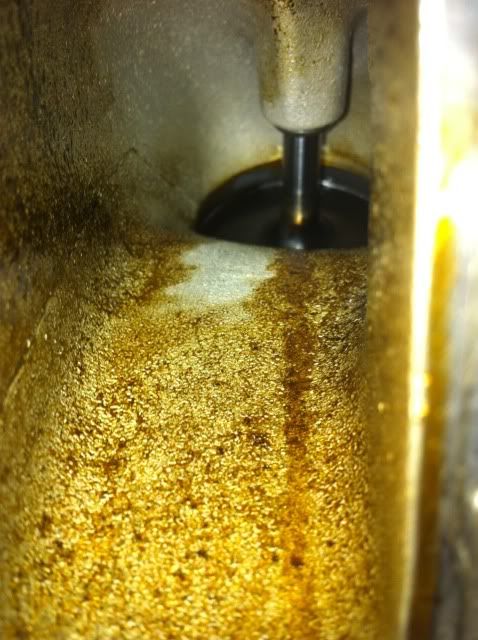
Picked up the heads yesterday. They look a million times better. There was a lot of sludge built up in the intake runners. The LS engines are notorious for bad PCV / oil consumption and these heads really showed it. I definitely need to build or buy a catch can / separator setup. I had him go ahead and lap the valves. I was a little on the fence because I don't think the lapped surfaces are quite as smooth as a properly ground valve & seat, but I think lapped will be better than what I had. He disassembled a couple valves so I could see the lapped surfaces and they looked good.
I spent some time BSing with Todd, the one-man-show that runs McKenzies Racing. He was a very nice guy to chat with and quite knowledgeable, not to mention gave me a great deal on the work. While I was there another guy was in the shop getting some LS1 heads rebuilt. He claimed he had a twin turbo '00 Camaro cranking 1,200hp on e85. We had some fun chit chatting about how his Manley crank reluctor wheel came loose, causing all kinds of interesting damage. There's just something great about BSing with car guys. I don't get enough of it.
At this point I am waiting on parts to arrive so I can finish the bottom end (new phaser & tensioner) and using what little free time I have to research next steps. Hope to see a lot of progress between now and Thanksgiving. It's going to be a blast.
11-08-2012, 01:56 PM
#594
Sounds like a great deal for $80. For that price I would be expecting them to only look in the neighborhood of 1000 times better.
BS'ing is pretty unecessary, life is serious business.. no time for kidding around.
All jokes aside, progress sounds great.. need moar picsss!!
All jokes aside, progress sounds great.. need moar picsss!!
11-08-2012, 03:04 PM
#595
Going on 460 photos in this thread as it is, but my woman is right - more wrenching less picture taking. Notice no photos of the heads up (yet), probably due to BSing.
 11-08-2012, 06:59 PM
#597

 11-09-2012, 03:04 AM
#598
Those pics look similar to what my LQ4 was doing with the stock PCV baffling setup. Hopefully with my LS6 valley cover most of the oil stays where it belongs.
Bandit= the guy with the Manley crank, did he have any troubles prior to the reluctor coming loose? When my Manley crank came in the reluctor was installed crooked. I ended up having the shop install a brand new GM reluctor. So far so good. Thanks for the info!
Bandit= the guy with the Manley crank, did he have any troubles prior to the reluctor coming loose? When my Manley crank came in the reluctor was installed crooked. I ended up having the shop install a brand new GM reluctor. So far so good. Thanks for the info!
11-09-2012, 12:56 PM
#600
For the Gen IV, you should use an LS3 valley cover. It has the improved baffling for PCV like the LS6, but without the knock sensor stuff. See image here: http://www.camaroperformers.com/proj.../photo_12.html
The stock LY6 pulls PCV from the driver's side valve cover. I think the Gen IV truck valve covers have better baffling than the Gen III (can anyone confirm?), but either way it seems the baffled valley covers are a better place to pull PCV than the valve cover. And even then a catch can (or catch cans) may be a good idea.
There is some good info here:
https://ls1tech.com/forums/generatio...outing-ok.html
I plan to run at least one catch can, but strongly considering two ("clean" and "dirty" side). I have some ideas for my own design.