
My 1965 Buick Skylark L92/6L80 Swap


 05-02-2013, 05:05 PM
#142

Thanks. The 64 Skylark should be pretty much the same. There are a couple of early Skylark builds on this site including Speedtiggers.
Here are some more pictures from today.
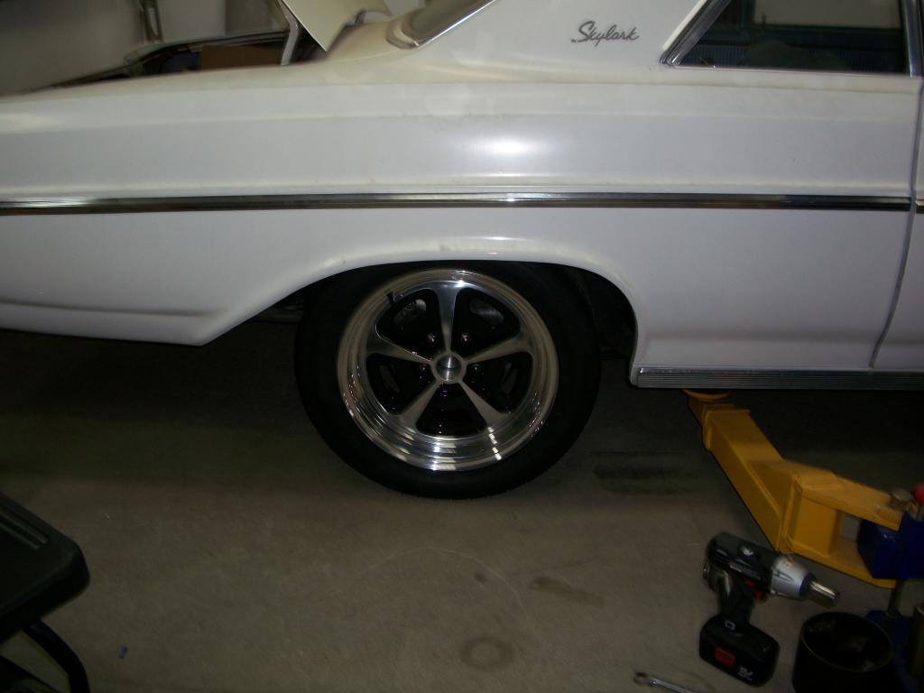
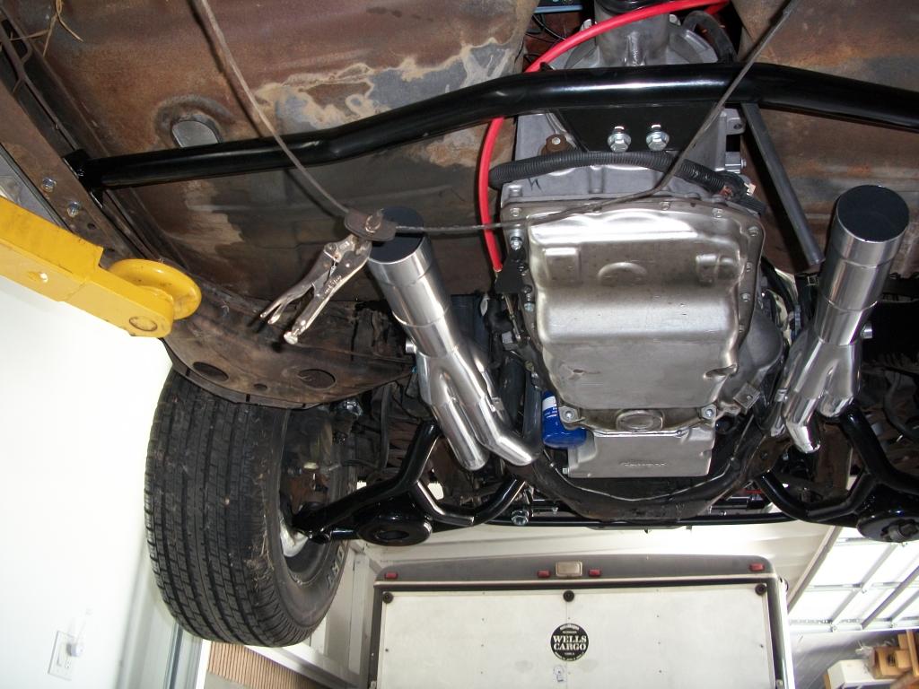
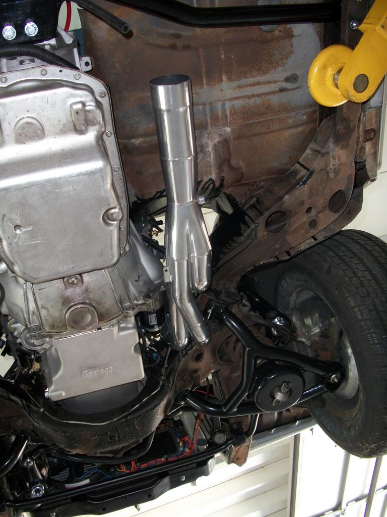
Picture of the VN500 wheel with the car on the ground.
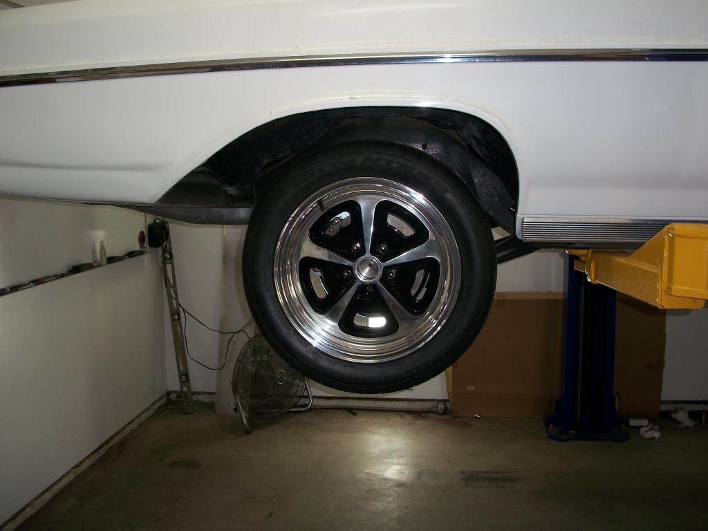
Picture of the wheel with the car in the air.
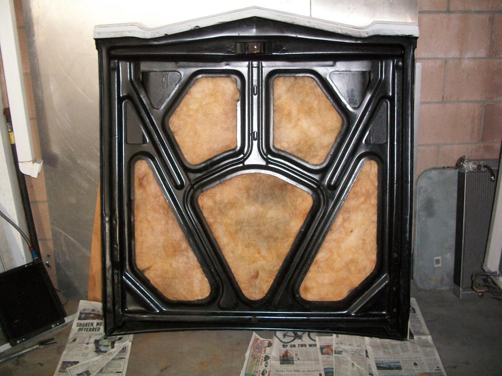
Forgot to post the bottom of the hood the other day.
Here are some more pictures from today.
Picture of the VN500 wheel with the car on the ground.

Picture of the wheel with the car in the air.

Forgot to post the bottom of the hood the other day.

Last edited by 1989GTA; 05-02-2013 at 09:11 PM.
05-02-2013, 05:13 PM
#143
Couple of more pictures from today.
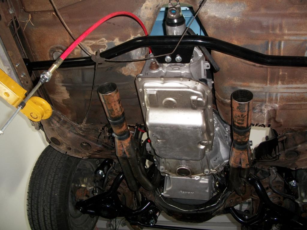
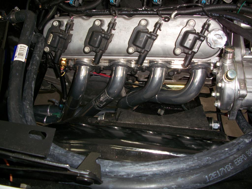
This one shows the bottom of the car with the collectors now attached to the header. I left them off incase I needed to change the angle a degree or two for a better fit. In reality the angle was pretty good and not much adjustment was needed. Here is the picture.
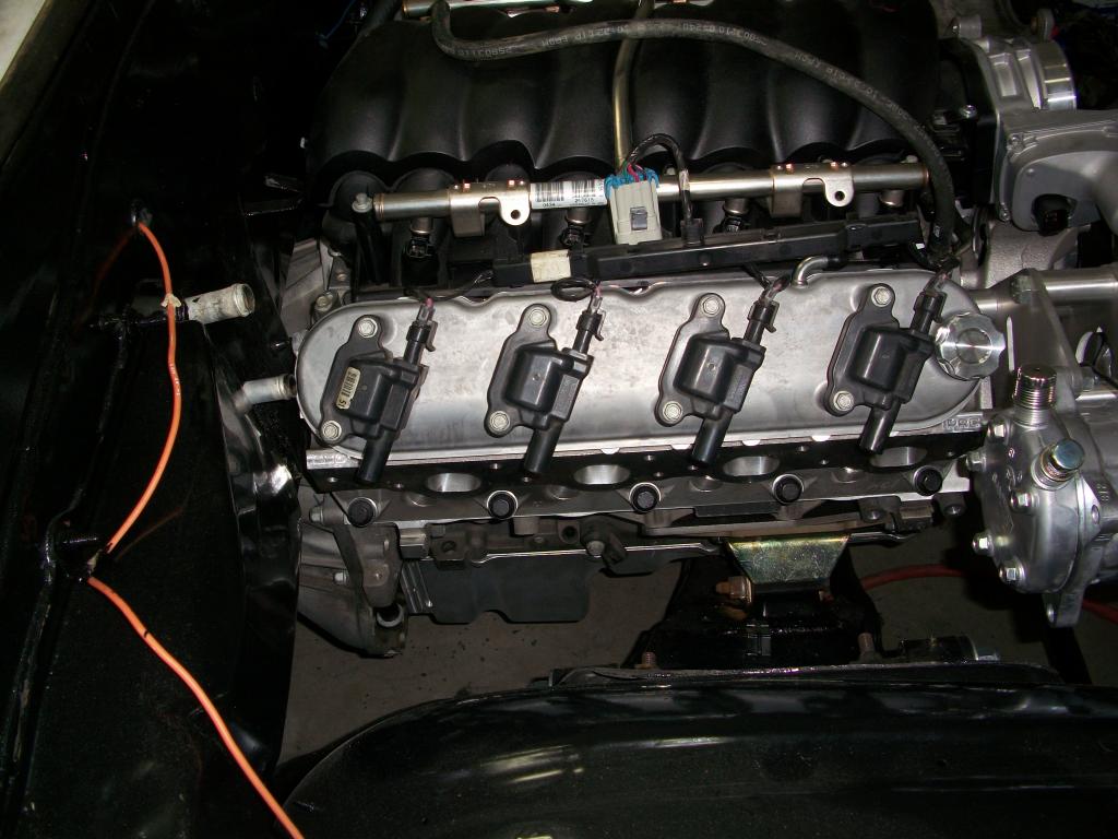
This picture shows the Holley valve covers. The reason I put them on was mainly to give me more clearance for the lower heater hose. Also it looks cleaner with the metal bracket removed. I forgot to say that we added a 1/8" shim under the transmission mount to help with the trans ground clearance. That made the lower heater hose very tight so I bought the Holley valve covers to give us more options in that area.

Last edited by 1989GTA; 05-02-2013 at 09:10 PM.
 05-03-2013, 04:13 PM
#146
"I'm really digging the wheel selection"
Thanks, they look like an updated version of the stock rally wheels and the reason for the selection. Trying to keep a pretty much stock look to the car.
"How much room do you have between the headers and the starter??"
I don't know yet. Looks like there is enough room though. The headers have gone out for a ceramic thermal coating application inside and out. Probably mount the starter on Monday. It is pretty small and I do have the heat shield for it. Should have an answer maybe on Thursday.
05-03-2013, 11:07 PM
#147
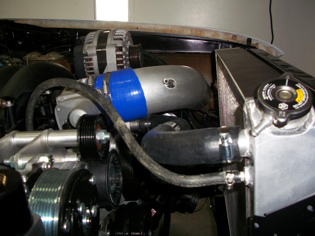
I about had a heart attack after I installed the alternator. I had no idea it was going to be so high. We put the hood on and there is going to be about a 1/2" of clearance. Whew, as things were going to smooth and I thought I had hit my first snag but dodged the bullet this time. By the way we decided on a 5" backspace with the 17 x 8 front wheels.
05-06-2013, 05:48 PM
#148
More progress pictures from today.
First up the new drive shaft is in.

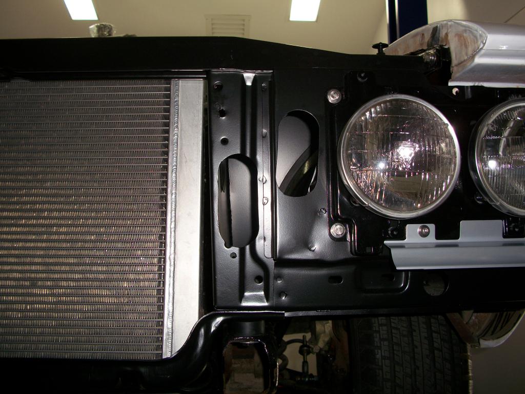
These are the holes we cut in the core support to increase the cold air flow to the air filter.
This one shows the gap between the upper radiator hose and the cold air intake tubing. I thought there might be a problem but not so. Plenty of room.
First up the new drive shaft is in.

These are the holes we cut in the core support to increase the cold air flow to the air filter.

This one shows the gap between the upper radiator hose and the cold air intake tubing. I thought there might be a problem but not so. Plenty of room.

Last edited by 1989GTA; 05-06-2013 at 08:17 PM.
05-06-2013, 05:53 PM
#149
...and three more pictures from today.
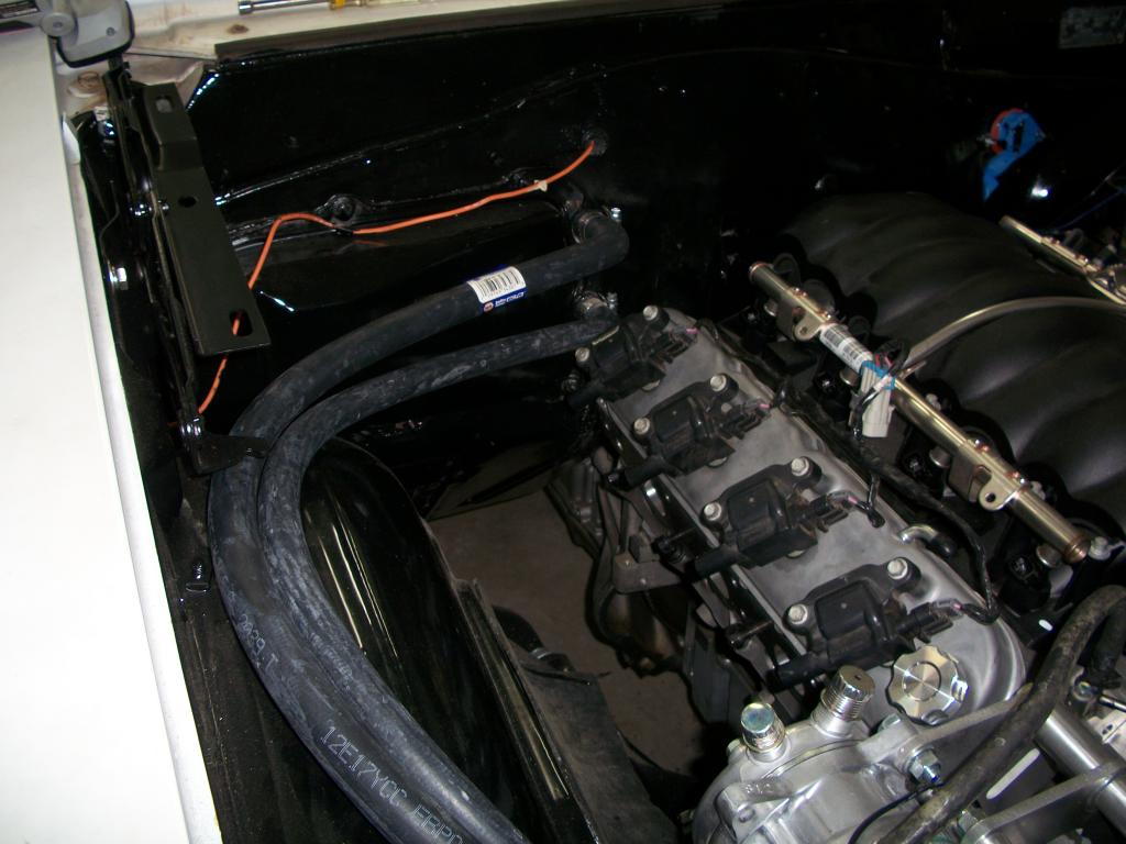
This one shows the heater hoses installed. Went with 90's right off the heater outlets. Worked out real well for this installation.
Here is a picture of the upper radiator hose.
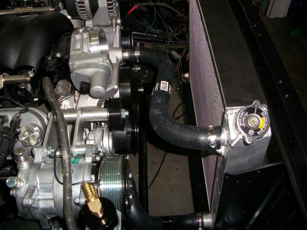
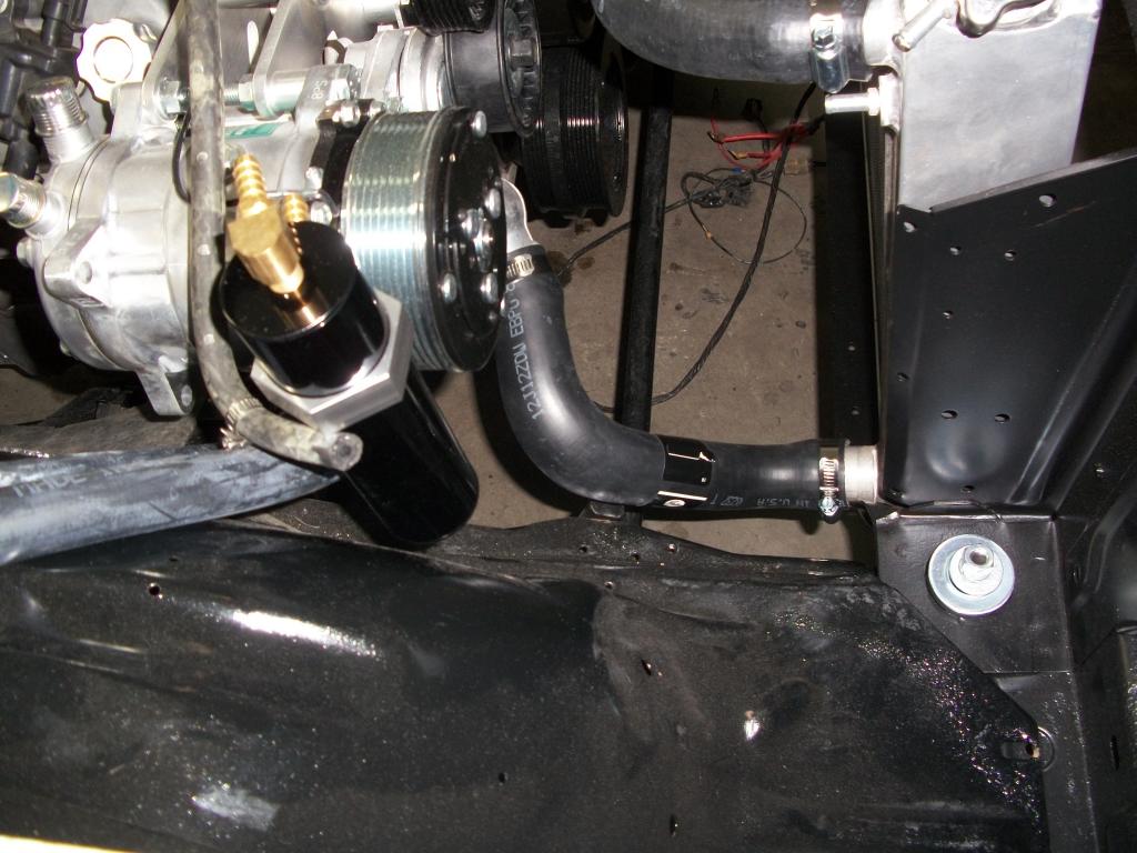
And finally a picture of the lower radiator hose. Still working on the serpentine belt. Looks like it will be around 114-115 inches.
This one shows the heater hoses installed. Went with 90's right off the heater outlets. Worked out real well for this installation.

Here is a picture of the upper radiator hose.

And finally a picture of the lower radiator hose. Still working on the serpentine belt. Looks like it will be around 114-115 inches.
 05-07-2013, 04:41 AM
#150
TECH Enthusiast

Not sure if you plumbed the transmission yet but S&P makes an adaptor to convert to 6an off the trans, also I used a g8 pan and pickup for the trans. I cant tell by the pics which pan you have but I had to change mine ,it was way to close for comfort , JOHN
05-07-2013, 10:01 AM
#151
Thanks John. Yes I do have the 6an adaptor for the transmission cooling lines. Right now I am using the truck pan on the transmission. I will wait and see how the car sits before making a final decision on the trans pan.
05-09-2013, 06:10 PM
#152
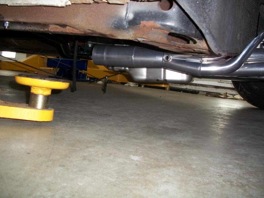
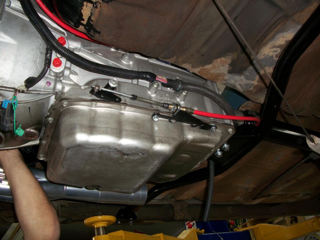
More photographs from today's session. This picture shows the ground clearance between the floor and the bottom of the 6L80 transmission. I would say between 5 and 6 inches.
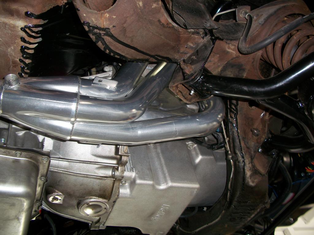
This picture shows the drivers side header from above now coated. Plenty of clearance.
This picture shows the underside of the drivers side header. Again plenty of room.

This picture shows the drivers side header from above now coated. Plenty of clearance.

This picture shows the underside of the drivers side header. Again plenty of room.
 05-09-2013, 06:17 PM
#153
3 more pictures from today.
With this picture I was trying to show the passenger header clearance versus the starter. The picture did not turn out like I thought it would. Anyways plenty of room even with the heat shield on the starter. We had to trim the forward part of the heat shield to match the contour of the header for it to fit.
Maybe a better view with this picture of the starter/ heat shield clearance.
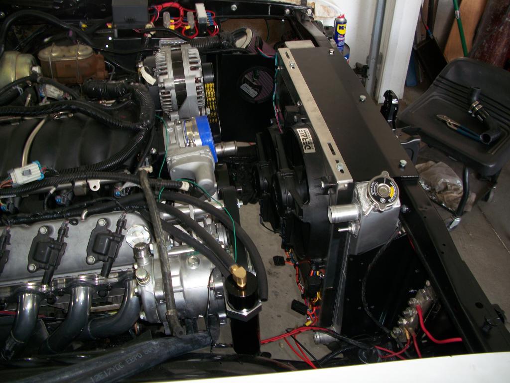
The next picture shows the fans and radiator installation. At this point it was not completely bolted in and the hoses were yet to be installed.
With this picture I was trying to show the passenger header clearance versus the starter. The picture did not turn out like I thought it would. Anyways plenty of room even with the heat shield on the starter. We had to trim the forward part of the heat shield to match the contour of the header for it to fit.

Maybe a better view with this picture of the starter/ heat shield clearance.

The next picture shows the fans and radiator installation. At this point it was not completely bolted in and the hoses were yet to be installed.

Last edited by 1989GTA; 05-09-2013 at 06:37 PM.
05-09-2013, 06:28 PM
#154
And the last three pictures from today.
This picture is a top view of the passenger side header. The headers not only got coated on the outside but also a thermal barrier coating on the inside.
This picture shows the Ididit transmission shift linkage. We had to modify the bracket so that it would fit the 6L80 transmission. Works just fine with the column shift.
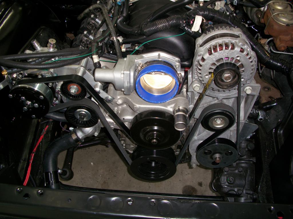
This picture shows the serpentine belt installation. Turned out we had to do some work to make this happen. The belt turned out to be 117.5" long. We had to move the idler pulley that is above the power steering pulley up and inch to take up the slack. The idler pulley is on the Dirty Dingo relocation bracket. Had to drill and tap a new hole in the bracket. Before we were in no-mans land on the serpentine belt length at around 116". You can't get them between 115" and 117.5". The easiest thing to do was to relocate the idler pulley so that we could get back into range of the available serpentine belts.
This picture is a top view of the passenger side header. The headers not only got coated on the outside but also a thermal barrier coating on the inside.

This picture shows the Ididit transmission shift linkage. We had to modify the bracket so that it would fit the 6L80 transmission. Works just fine with the column shift.

This picture shows the serpentine belt installation. Turned out we had to do some work to make this happen. The belt turned out to be 117.5" long. We had to move the idler pulley that is above the power steering pulley up and inch to take up the slack. The idler pulley is on the Dirty Dingo relocation bracket. Had to drill and tap a new hole in the bracket. Before we were in no-mans land on the serpentine belt length at around 116". You can't get them between 115" and 117.5". The easiest thing to do was to relocate the idler pulley so that we could get back into range of the available serpentine belts.

Last edited by 1989GTA; 05-10-2013 at 07:42 PM.
05-10-2013, 11:33 AM
#156
How have I not found your thread until now?
Lots of great work. The instrument cluster turned out incredible! Subscribing to the thread now. I see a lot of details in the background areas of the images I'd love to hear more about. For example, your wiring & fuse/relay center and the PCV catchcan.
I am digging the VN500s. I am strongly considering the YearOne magnums for my Nova - very similar style but without the polish of the AR version.
Keep up the progress!
05-10-2013, 05:15 PM
#157
Thanks Speedtigger. One thing to remember for those doing research that to make the Heddman headers work(and maybe other brands to) I needed the Dirty Dingo Sliders and the tall and narrow mounts. That way we could position the motor exactly where we wanted it to give the headers equal clearance all around. I also made my own merge collector from Cone Engineering parts. I also bought the headers un-coated incase I needed to massage them. Turned out I did not need to.
05-10-2013, 05:30 PM
#158
"For example, your wiring & fuse/relay center and the PCV catchcan."
The PCV catch can is from Mike Norris. I had to modify the catchcan bracket slightly to fit on my compressor bracket. Basically drill a new hole closer in to the catchcan. Then cut off the remaining outside portion.
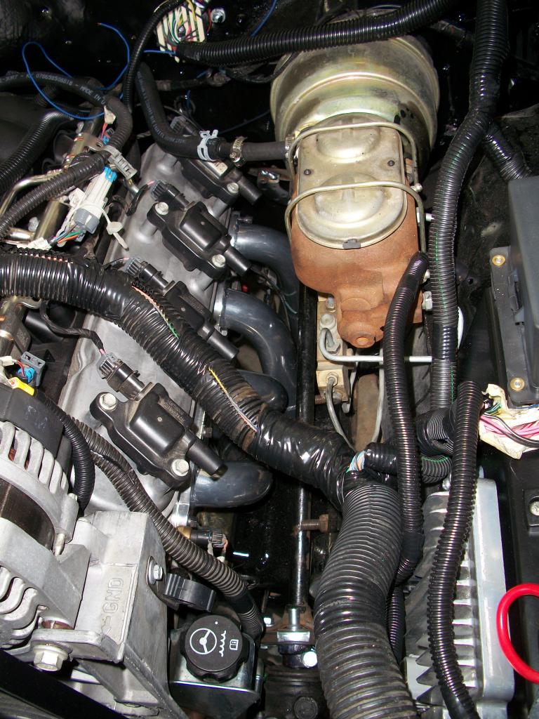
The wiring and fuse/relay center is more complicated to explain. As you can see it is the Bussman relay/fuse box. I have two high amp relays in there. One is the power train relay and the other is the run/crank relay. I have ten fuses on the back side fed by one power strip. The power train relay powers the strip. I also was able to fit 3 independent fuses between the relays. One is transmission #20, 2nd is ECM #58 and the last is for the fuel pump relay coil. I tried to follow the factory wiring best I could including the correct color codes on the wires.
The two terminal strips are battery and ignition. I had to add a 3rd terminal strip for more fuses. That strip is battery fed. The wiring is basically the 2009 Escalade engine wiring harness that I modified. I added a harness to go inside to the dash area. You can see the Painless bulkhead fitting on the firewall. The bulk of that wiring is for the gauges, gas pedal and communication wires plus power and ground.
The PCV catch can is from Mike Norris. I had to modify the catchcan bracket slightly to fit on my compressor bracket. Basically drill a new hole closer in to the catchcan. Then cut off the remaining outside portion.
The wiring and fuse/relay center is more complicated to explain. As you can see it is the Bussman relay/fuse box. I have two high amp relays in there. One is the power train relay and the other is the run/crank relay. I have ten fuses on the back side fed by one power strip. The power train relay powers the strip. I also was able to fit 3 independent fuses between the relays. One is transmission #20, 2nd is ECM #58 and the last is for the fuel pump relay coil. I tried to follow the factory wiring best I could including the correct color codes on the wires.
The two terminal strips are battery and ignition. I had to add a 3rd terminal strip for more fuses. That strip is battery fed. The wiring is basically the 2009 Escalade engine wiring harness that I modified. I added a harness to go inside to the dash area. You can see the Painless bulkhead fitting on the firewall. The bulk of that wiring is for the gauges, gas pedal and communication wires plus power and ground.
05-10-2013, 06:03 PM
#159
Thanks Speedtigger. One thing to remember for those doing research that to make the Heddman headers work(and maybe other brands to) I needed the Dirty Dingo Sliders and the tall and narrow mounts. That way we could position the motor exactly where we wanted it to give the headers equal clearance all around. I also made my own merge collector from Cone Engineering parts. I also bought the headers un-coated incase I needed to massage them. Turned out I did not need to.
05-10-2013, 07:47 PM
#160
The person who is doing my car in his shop knows a local coating place that he does a lot of business with. He took them over there. I have also used a shop in Huntington Beach, California on previous projects. There are many shops around the country who do this. It is becoming quite common. I am sure there are a few shops there in Florida who do ceramic coatings.