
Custom Long Tube Header / Exhaust Build ***DYNO Results are In***
 06-17-2013, 12:14 AM
#81
Staging Lane
Join Date: Jul 2012
Location: Bakersfield, CA
Posts: 84
Likes: 0
Received 0 Likes
on
0 Posts
 06-17-2013, 10:01 AM
#82
11 Second Club
Thread Starter
 06-17-2013, 05:40 PM
#84
Great build, I love working with tubing, especially SS.
markbsae took the words right out of my mouth, donuts are great.
These also might come in handy if you're doing a lot of exhaust work
http://www.icengineworks.com/icewmain.htm
More
http://www.coneeng.com/pdf/Collector...ents%20PDF.pdf
http://www.coneeng.com/exhaust_system_kits.html
And you can always rely on Burns
06-17-2013, 07:37 PM
#86
11 Second Club
Thread Starter
These also might come in handy if you're doing a lot of exhaust work
http://www.icengineworks.com/icewmain.htm
More
http://www.coneeng.com/pdf/Collector...ents%20PDF.pdf
http://www.coneeng.com/exhaust_system_kits.html
http://www.icengineworks.com/icewmain.htm
More
http://www.coneeng.com/pdf/Collector...ents%20PDF.pdf
http://www.coneeng.com/exhaust_system_kits.html
Funny you mentioned them.. I used all 3 of those in this very build
 06-18-2013, 08:27 AM
#87
TECH Enthusiast

Join Date: Feb 2007
Location: Raleigh, NC
Posts: 625
Likes: 0
Received 0 Likes
on
0 Posts

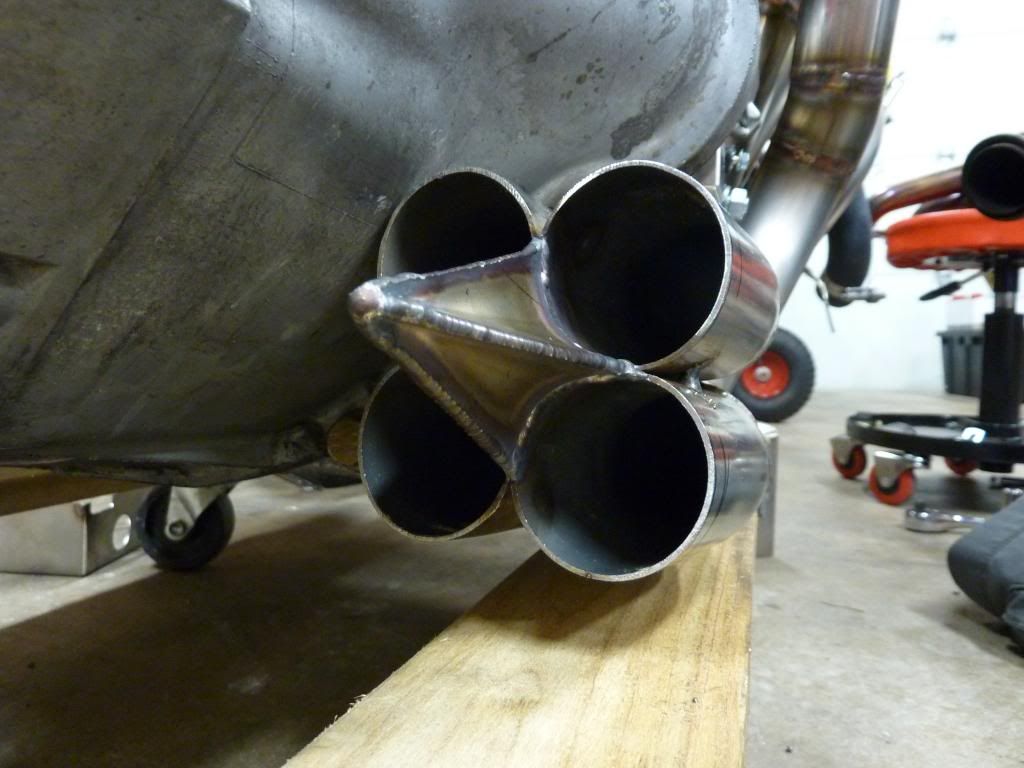
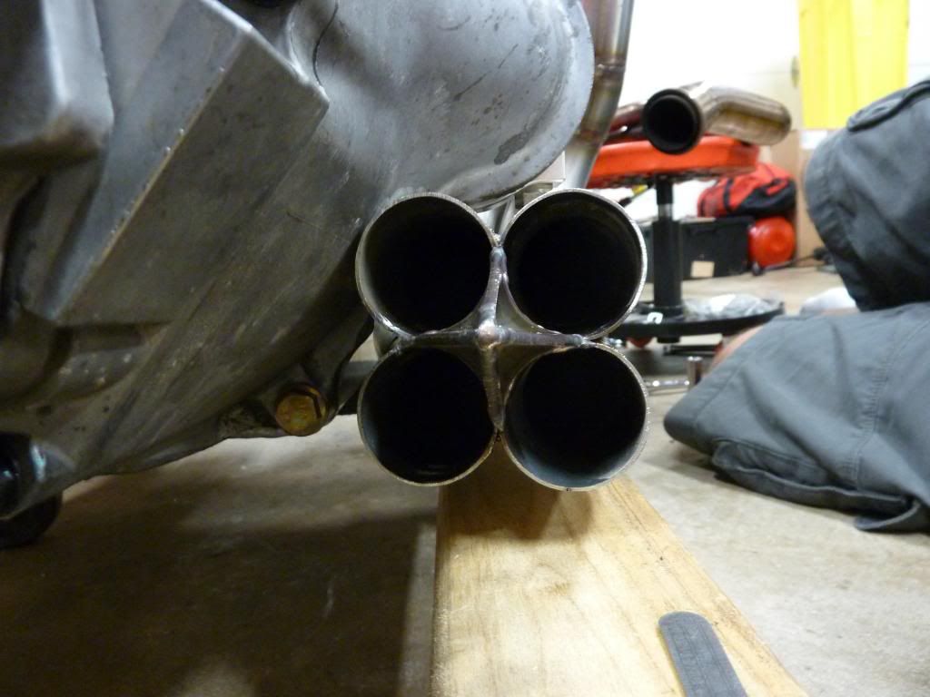
I was finally able to get some work done on the headers this weekend.
First I tacked all the primaries into their final position and cut the end off all the tubes so they were even. Then I tacked the collector bullets into place.
I also tacked together the 2 collector parts.
The plan is to have the bullets and collectors TIG'ed separately, then once I get them back, I'll tack on the collectors to ensure everything fits right.
It doesn't seem like much work but once you consider how many times I've had the engine in and out, the time adds up pretty quick. I'd easily put this little project higher on the difficulty scale than the whole V8 swap.
edit - duh, I missed your last post about being the Megs / Cone parts.
So, how do you like them?
Thanks
06-18-2013, 09:42 PM
#88
11 Second Club
Thread Starter
No complaints so far. Seems to be good quality and everything arrived quickly and well packed.
.....and 1/2 the price of the Stainless Works slip-on's that I originally bought.
.....and 1/2 the price of the Stainless Works slip-on's that I originally bought.
07-05-2013, 10:52 PM
#89
11 Second Club
Thread Starter
Got the headers back from the welder again with the collector bullets all TIG'ed up! The next step is to bolt them back up and put the engine back in so I can tack the collectors into their final position.
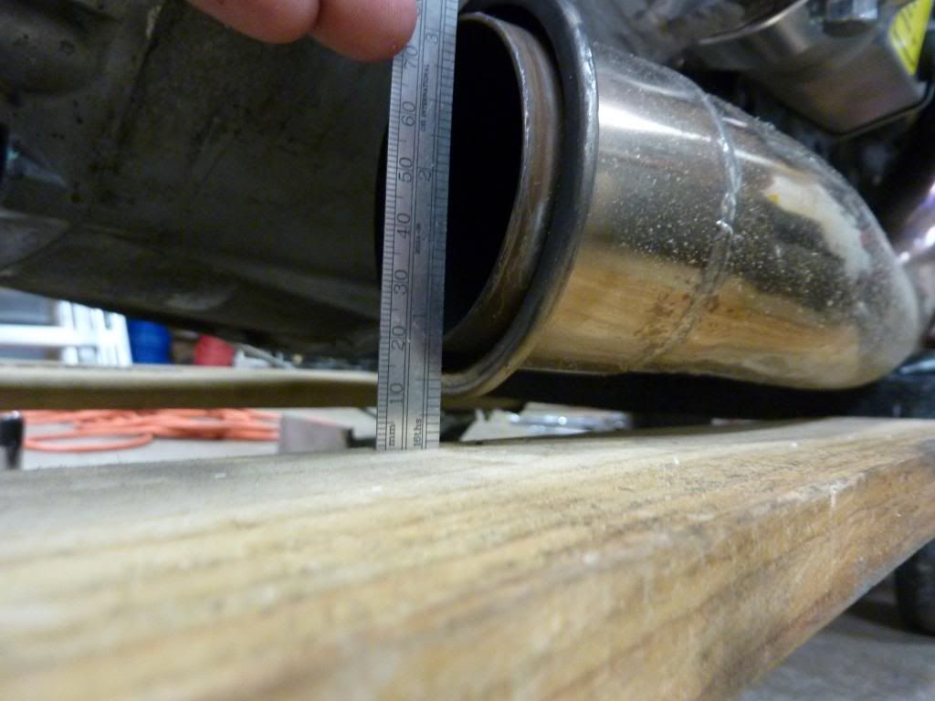
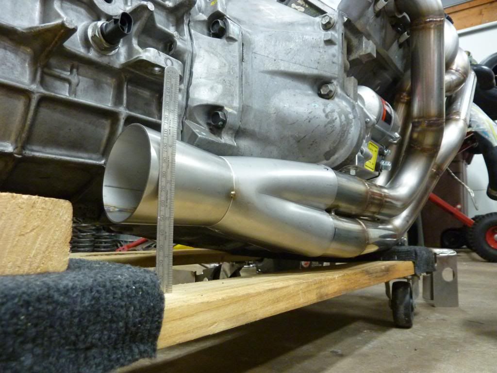
To get a ground clearance comparison I installed the old and new headers back to back.
First the Flyin Miata shorties. You can see the lowest point is right where the V-band connects to the mid-pipe. With the clamp in place you lose an additional ~1/4" or so.
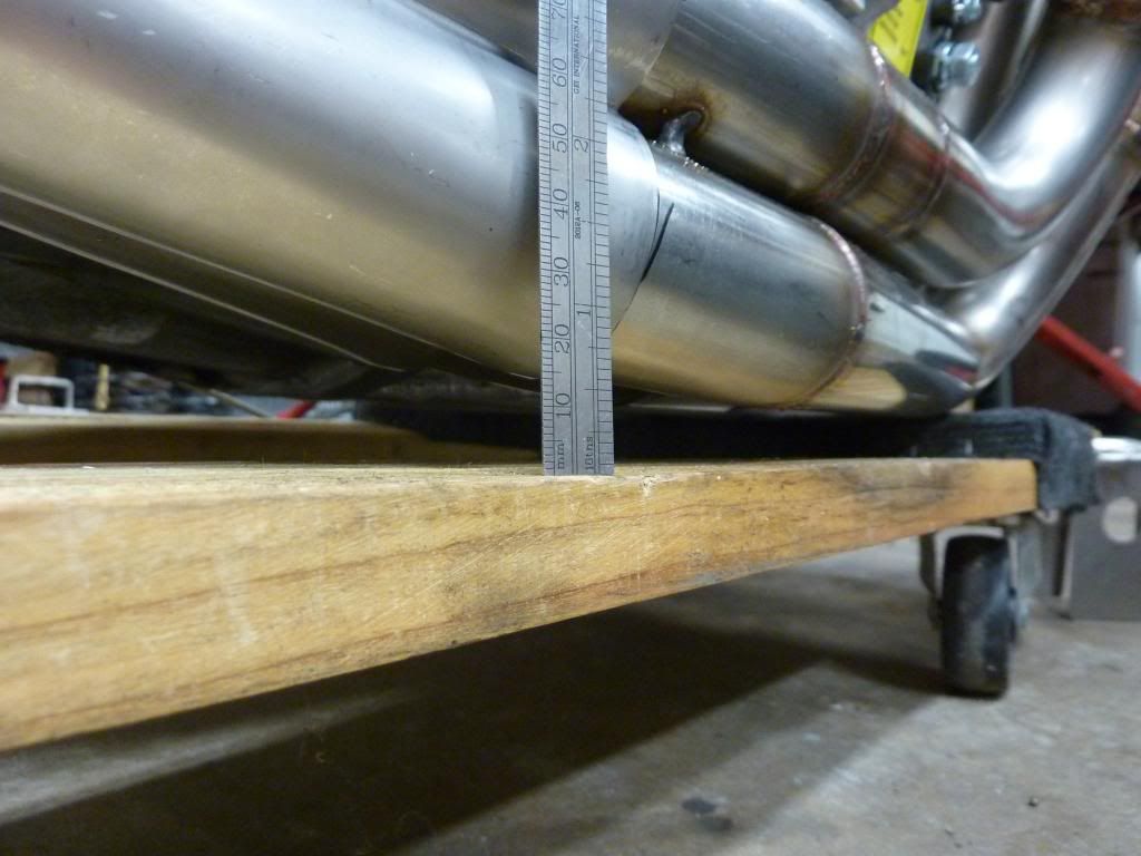
Next my headers. At the lowest point there's roughly 1/2" more clearance. The V-bands are placed further back and should have plenty of clearance. The final angle might be pointed down a little more but not much.

 07-08-2013, 08:56 PM
#90
11 Second Club
Thread Starter
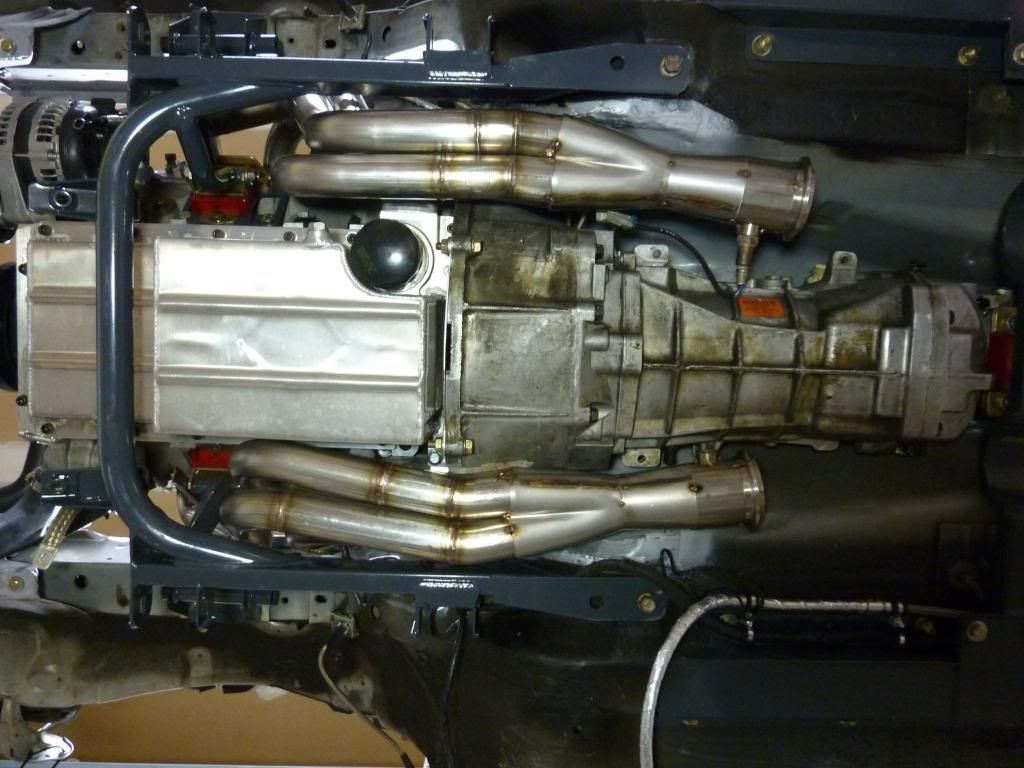
Spent the day getting the collectors and V-bands tacked in place.
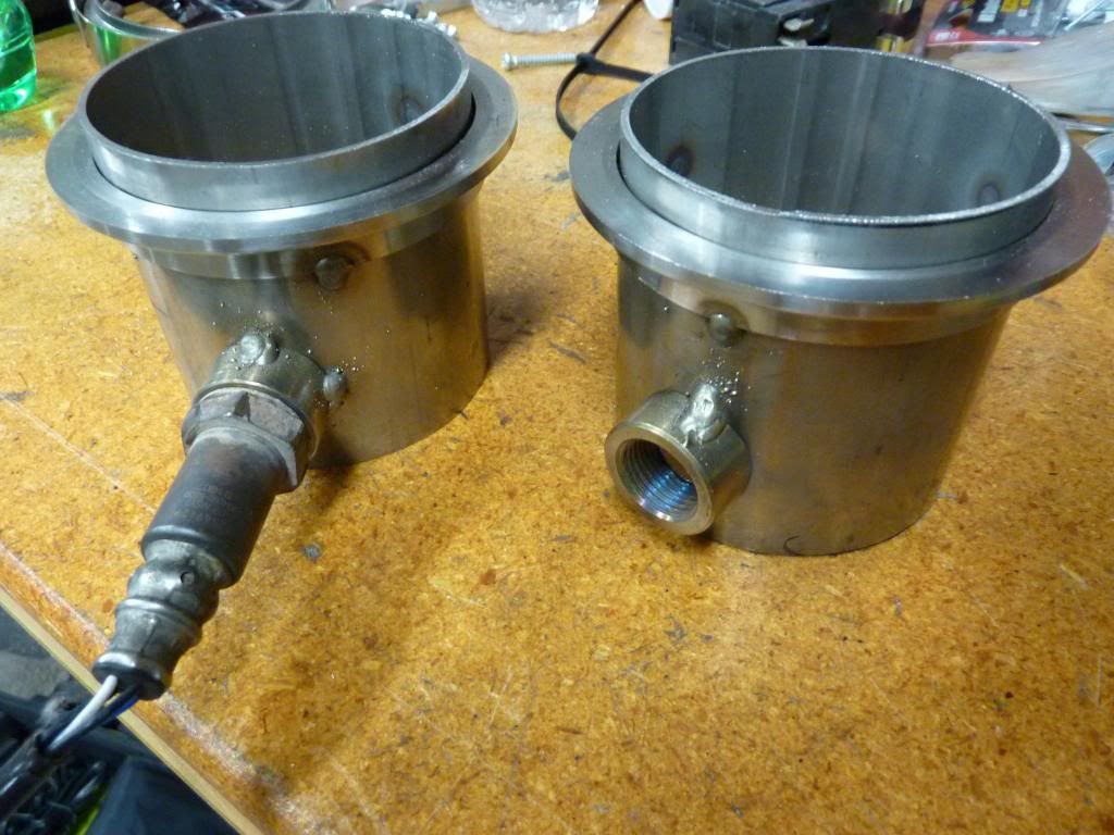
Here's a shot of the 02 bungs and V-bands tacked on. This small section of pipe will be tacked onto the end of the collectors.
Tacked them onto the collectors, here's how it looks now.
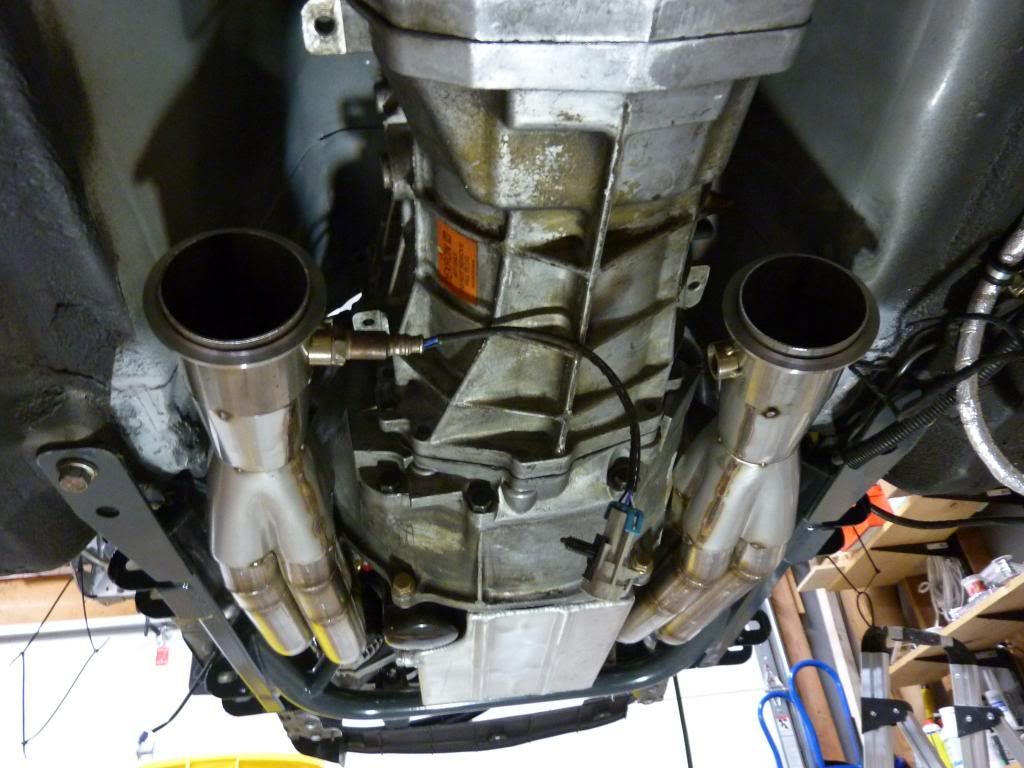
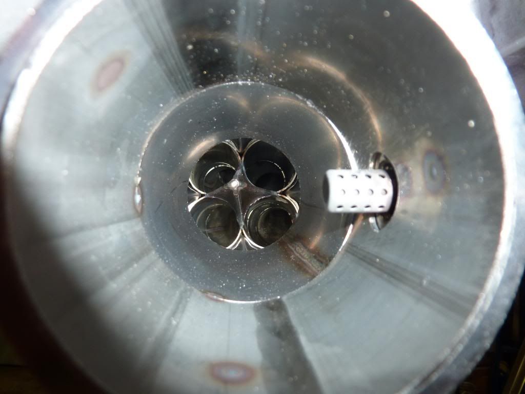
And a shot of the inside of the collector with 02 sensor. I wanted to get the 02's up a little higher but it wasn't possible. If I pointed them straight up there would have been no way to get a wrench on them. 9:00 and 3:00 position will have to do.
Here's a shot of the 02 bungs and V-bands tacked on. This small section of pipe will be tacked onto the end of the collectors.

Tacked them onto the collectors, here's how it looks now.


And a shot of the inside of the collector with 02 sensor. I wanted to get the 02's up a little higher but it wasn't possible. If I pointed them straight up there would have been no way to get a wrench on them. 9:00 and 3:00 position will have to do.


 07-09-2013, 09:31 PM
#94
11 Second Club
Thread Starter


 07-22-2013, 07:52 AM
#98
11 Second Club
Thread Starter
Well, looks like I have yet another obstacle before I can move forward. While the header welds look beautiful, it seems that the flanges are now slightly warped. Specifically the drivers side at cylinder #7.
Seems like there are a couple options to fix them.
-Bolt them up to some old heads and heat them up while tightening down the bolts.
-Mill the flanges. (probably not a bad idea anyway once they are straightened)
-Make cuts between the cylinders to separate them making it easier to tighten the warped cylinder.
Silly me for thinking 1/2" flanges would be warp-proof...
07-22-2013, 10:15 AM
#100
TECH Enthusiast
Join Date: Feb 2007
Location: Raleigh, NC
Posts: 625
Likes: 0
Received 0 Likes
on
0 Posts
Well, looks like I have yet another obstacle before I can move forward. While the header welds look beautiful, it seems that the flanges are now slightly warped. Specifically the drivers side at cylinder #7.
Seems like there are a couple options to fix them.
-Bolt them up to some old heads and heat them up while tightening down the bolts.
-Mill the flanges. (probably not a bad idea anyway once they are straightened)
-Make cuts between the cylinders to separate them making it easier to tighten the warped cylinder.
Silly me for thinking 1/2" flanges would be warp-proof...
Seems like there are a couple options to fix them.
-Bolt them up to some old heads and heat them up while tightening down the bolts.
-Mill the flanges. (probably not a bad idea anyway once they are straightened)
-Make cuts between the cylinders to separate them making it easier to tighten the warped cylinder.
Silly me for thinking 1/2" flanges would be warp-proof...
Either heating or milling will work, but heating the flange to make the flange flat puts more stress in the tubes which can make them crack after long term use.
I'd mill them. It's the most reliable long term option, which if I were to guess, is probably why you built with stainless to begin with.
And nothing is warp proof.