
New Hooker 1st-gen/Nova swap parts info
 10-13-2014, 06:13 PM
#141
Teching In
iTrader: (2)

Join Date: Mar 2010
Location: Southern California
Posts: 33
Likes: 0
Received 0 Likes
on
0 Posts
Don't be overly concerned with the position of your subframe when taking your engine inclination reading as it is only a baseline point of reference to get you started. Your engine would function at 20 degrees down angle so you should understand the main point of your focus should merely be to optimize your U-joint working angles, which need to be at least 1/2 a degree, less than 3 degrees each (the closer you can get to 1/2 a degree the better) and the same to one another within 1/2 a degree also unless you're setting up a leaf spring car for racing. Leaf spring cars set up for racing typically run a few extra degrees of pinion down angle to compensate for spring wrap under acceleration.
 10-14-2014, 04:15 AM
#142
TECH Junkie
Thread Starter

Ok Todd will keep that in mind also. Was under the car over the weekend looking at what I can plan for my crossmember and I came up with something. Have a few question I thought I might ask, plan on using 1"x2" rectangular tubing and what thickness would you recommend at minimum and 1/4 angle iron to attach to subframe. Looks like it will tuck up nicely but now need to get material. Thanks Todd
10-14-2014, 07:17 AM
#143
Teching In
iTrader: (2)
Join Date: Mar 2010
Location: Southern California
Posts: 33
Likes: 0
Received 0 Likes
on
0 Posts
I don't know what you have in mind conceptually or which way you plan to orientate the 1" x 2" tubing, so that makes giving you a recommendation difficult. In general, I wouldn't use anything less than .120" wall tubing if you are using typical low carbon steel. That is assuming you are crossing the span with a straight non-cantilevered beam design.
10-14-2014, 09:52 AM
#144
TECH Junkie
Thread Starter
Yes Todd I am spanning straight across, using a few 45 deg angles to tuck up to floor. Then back down & welded to my 3/16 - 2 x 3 angle iron which will be bolted to the bottom of subframe using 7/16 or greater bolts thru frame. How much clearance should I allow for trans travel upward, I'm using the stock rubber trans mount. I have to trim some of the original cross bracing above end of trans and then reinforce area for an about 1-3/8" clearance just in case of movement upward. Also have to modify trans tunnel for driveshaft for clearance also. Appreciate your insight in this little but touchy project. Thank you.
10-14-2014, 10:14 AM
#145
Teching In
iTrader: (2)
Join Date: Mar 2010
Location: Southern California
Posts: 33
Likes: 0
Received 0 Likes
on
0 Posts
If you are using the Hooker 1st-gen F-body/ 3rd-gen Nova LS engine swap brackets, you won't have to cut any part of the car/body to install the 4L80 at an optimized angle (I've already done it). If you are using some type of swap plate engine mount set-up, you may want to consider switching to the Hooker brackets to save yourself a lot of grief, aggravation, time and money. If you are sold on cutting up your floor, then my advice is to get the engine and trans in the car at the height you want them at and just build the crossmember up to the mount; there is no need to allow for extra space above the trans if you measure and set your inclination/U-joint working angles before you start building the crossmember.
 I will get on it this weekend and let you know how it comes out. Thanks
10-26-2014, 12:49 AM
I will get on it this weekend and let you know how it comes out. Thanks
10-26-2014, 12:49 AM
#147
Teching In
iTrader: (2)
Join Date: Mar 2010
Location: Southern California
Posts: 33
Likes: 0
Received 0 Likes
on
0 Posts
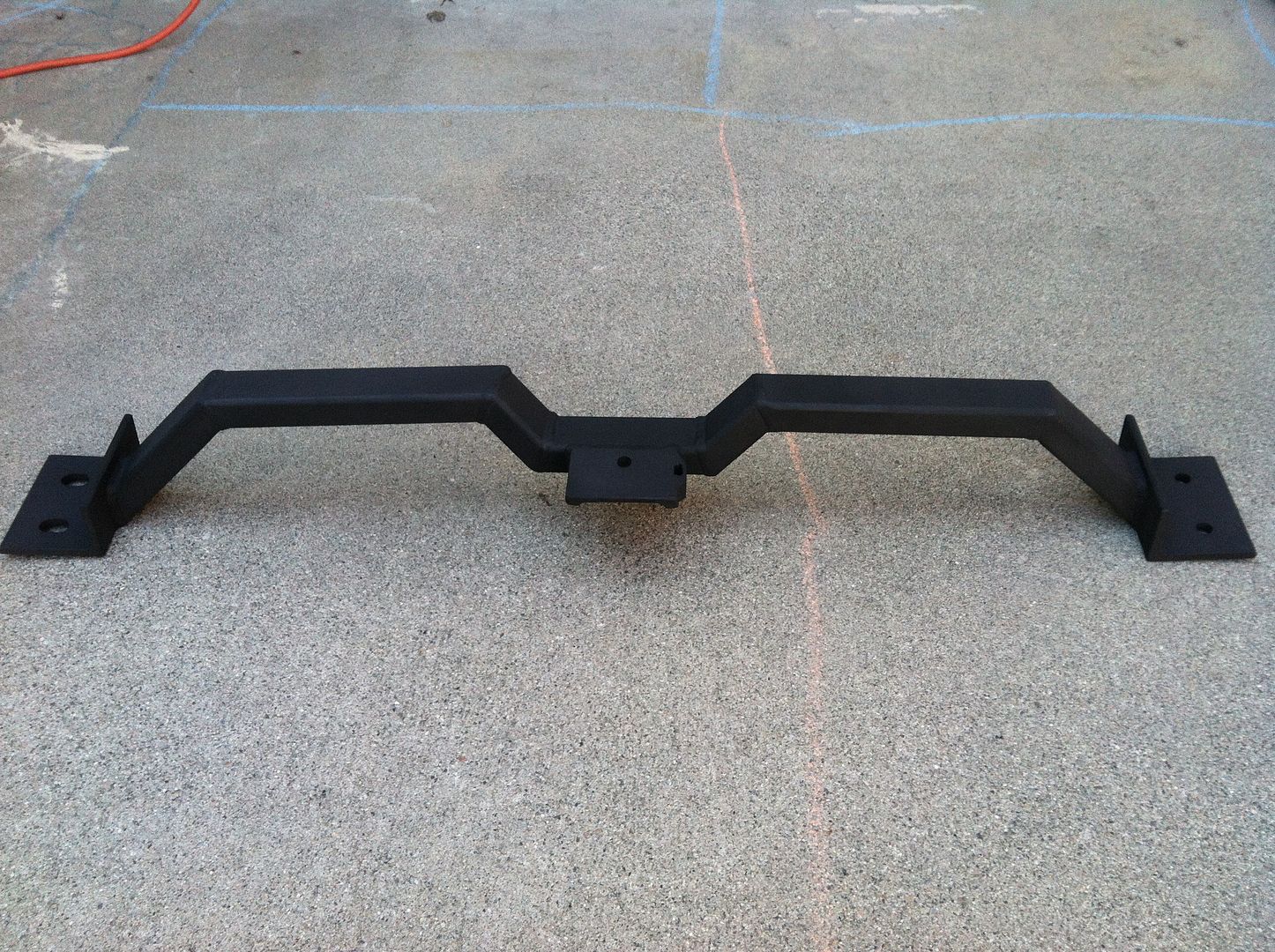
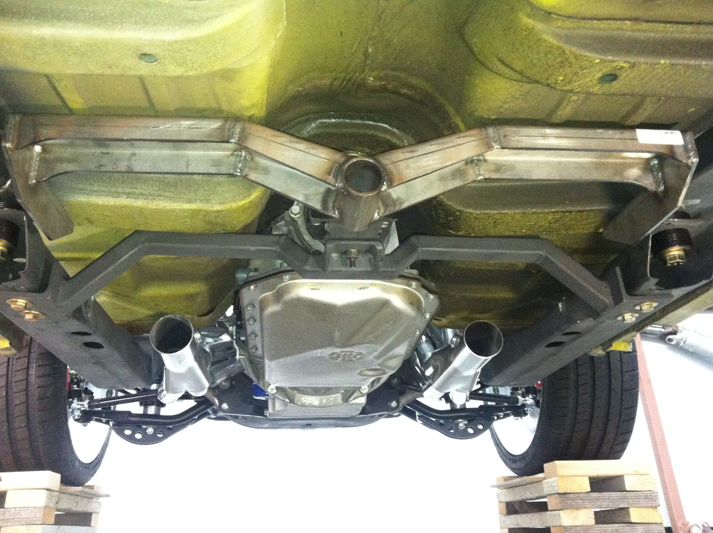
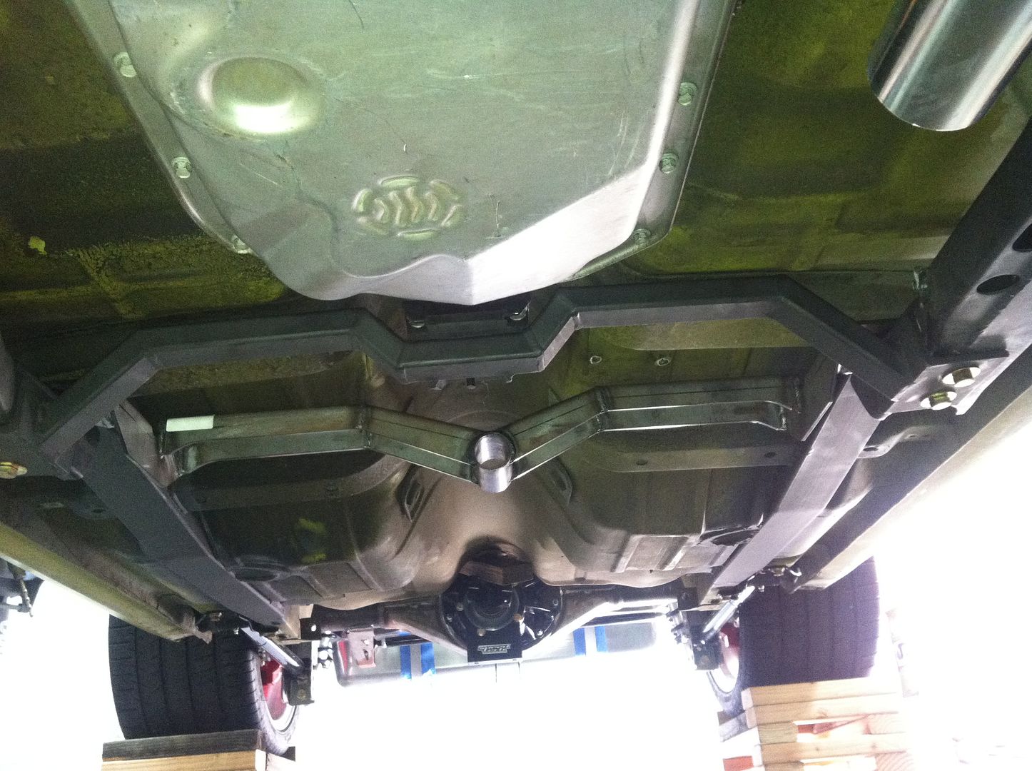
We'll I've finished up my trans crossmember for 4L80E in my Nova, it's not the best engineered but I think it will do just fine. Want to thank Todd for answering all my questions and giving me good info. Thanks.


 10-26-2014, 10:09 AM
#148
TECH Junkie
Thread Starter
Nice work, that should serve you just fine. You were fortunate to have the higher floor pan of the Nova working in your favor; the F-body floor is pancaked down on top of the subframe and doesn't provide the same freedom of space to work in. That constraint is what created the need for the considerable design effort behind the Hooker 4L80 crossmember for these applications that I'll soon be previewing here and be releasing in the near future. The only advice I would have lent to your design efforts up-front would have been to make the unit a two-piece design so your mounting angles could have been located on top of the subframe and the mounting holes drilled through the side walls of the subframe.
11-03-2014, 11:58 AM
#149
Staging Lane

Join Date: Feb 2014
Posts: 55
Likes: 0
Received 0 Likes
on
0 Posts
Nice work, that should serve you just fine. You were fortunate to have the higher floor pan of the Nova working in your favor; the F-body floor is pancaked down on top of the subframe and doesn't provide the same freedom of space to work in. That constraint is what created the need for the considerable design effort behind the Hooker 4L80 crossmember for these applications that I'll soon be previewing here and be releasing in the near future. The only advice I would have lent to your design efforts up-front would have been to make the unit a two-piece design so your mounting angles could have been located on top of the subframe and the mounting holes drilled through the side walls of the subframe.
Great work kiquee!
Last edited by BlackHD; 11-03-2014 at 01:49 PM.
 01-05-2015, 01:17 PM
#156
TECH Junkie
Thread Starter
I can't give you a discrete measurement from that standpoint as the development vehicle used was delivered without the original engine or transmission in place from which a reference point would have been established. When an LS engine is installed using the Hooker engine brackets, the machined surface at the front of the engine block sits 1/2" behind the front wall of the engine crossmember and the rear surface of the right side cylinder head is approximately 1-1/2" from the firewall.
04-02-2015, 06:43 PM
#157

Todd
You mentioned in another post that using the F-body low mount alternator with these mounts requires notching the crossmember. Do you (or anyone that has done it) have a photo of the location, shape and depth of the required notch?
Thanks
You mentioned in another post that using the F-body low mount alternator with these mounts requires notching the crossmember. Do you (or anyone that has done it) have a photo of the location, shape and depth of the required notch?
Thanks
04-02-2015, 08:01 PM
#158
TECH Junkie
Thread Starter
I don't, as I attempted to install the F-body alternator and stopped once it became appearant that notching would be needed to make it happen.
01-13-2016, 02:54 PM
#159
TECH Fanatic
iTrader: (27)

Just bought my 12618HKR engine mounts and look forward to installing them in my 68 Camaro. I will be running the fbody accessories, so I can post some pictures of the notch and how large/small the notch has to be.
01-13-2016, 07:49 PM
#160
Staging Lane
iTrader: (6)

Join Date: Jul 2004
Location: Melbourne, Florida
Posts: 75
Likes: 0
Received 0 Likes
on
0 Posts

https://ls1tech.com/forums/conversio...8-74-nova.html