
Connector C100 G pin, Connector C105 B pin
 04-25-2008, 06:18 PM
#1
Teching In
Thread Starter

Join Date: Sep 2007
Location: dallas, tx
Posts: 22
Likes: 0
Received 0 Likes
on
0 Posts
hey sorry i don't post much but quick idea of what i have going on. s13 coupe, semi-built ls1 swap, drift car.
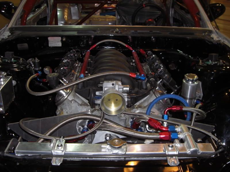
i'll have tons of cool pics when done but thats just general where i'm at status. all i have left is headers and wiring, so today i opted for the easier of the two and gutted the engine harness. its suprisingly easy on the ls1, i was going off an ecu pinout and everything was going great! i noticed some wires weren't listed on the ecu pinout, things like the c100/101/105 plugs weren't on there. i'm used to reading a normal Nissan FSM so this was confusing me. well i finally found the pinouts for the C10's plugs just a couple wires too late. i know where the locations are on the plugs for the wires i need, and they are as follows...
Connector C100, G pin (engine control power, route to IGN 3 15A fuse)
Connector C105, B pin (engine sensor power, route to IGN 5 20A fuse)
I assume Bpin on c105 doesn't go back to ecu, it goes back to one of the pink tangles of wires where 1 turns into 5 or whatever then splits into sensors, but i cannot find where in the harness this is exactly sense there's a COUPLE of these pink tangles of wire. Now, C100 G pin i'm totally lost on, i figured this one went straight to ecu however i was very wrong, i don't know where this one goes back into the harness. Nissan fsm shoots wiring traces as to where they go and i just simply cannot seem to find that, only pin #s. so i looked up pin #s for ecu battery constant and ignition 12v and sure enough they are there and sound and secure, actually mine are going to C101 so whatever that was a useless waste of time.
ok and after these things are taken care of, i need to know what to do with serial data (C105 E pin). do i even need the obdII scanner port? i plan on tuning with hptuners and have no idea how it communicated with ecu as i haven't bought anything yet so i didn't wanna cut that wire just yet. can i eliminate obdII port and still use hptuner or ls1edit or whatever i end up using?
thanks for the help in advance! i hope to become a more active member of this board soon, just been lurking in the mean time.

 04-27-2008, 12:34 AM
#3
Teching In
Thread Starter
Join Date: Sep 2007
Location: dallas, tx
Posts: 22
Likes: 0
Received 0 Likes
on
0 Posts
based on the pcm pinout i was using, didn't seem to be exactly 2000 or 2001, its a z28 and some of the wires correspond with 2001 but most with 2000. maybe it was during a wierd year change iunno?
05-15-2008, 01:29 PM
#5
Teching In
Thread Starter
Join Date: Sep 2007
Location: dallas, tx
Posts: 22
Likes: 0
Received 0 Likes
on
0 Posts
awesome, this has been handled. just bumping this to post up recomendations for people to deal with SPEARTECH if you have any wiring problems. john over there is super coooool, hooked it up with obdII connector/engine light, and answered some ?s i had about wiring. don't hesitate those dudes are awesome!
05-17-2008, 11:34 PM
#6
Teching In

Join Date: Jun 2007
Posts: 48
Likes: 0
Received 0 Likes
on
0 Posts

Don't know if this will help but the two wires your trying to find homes for do not go to the PCM.
Connector C100, G pin (engine control power, route to IGN 3 15A fuse)
Connector C105, B pin (engine sensor power, route to IGN 5 20A fuse)
99 LS1 PCM to Dash Harness
White (220) Plug
A TAN Oil Pressure
B GRY PCM 32 Clutch Anticipate Switch Signal
C PNK C105-B IGN Power for TCC Stop Lamp Switch
D PPL PCM 33 TCC/Cruse Brake Switch
E BLK/WHT
H ORN/BLK PCM 34 PNP Switch Signal
J YEL/BLK Low Coolant Indicator
K DK GRN/WHT PCM 50 VSS Output
Blue (230) Plug
A GRY PCM 46 5V Feed (Fuel tank pressure)
B BRN/WHT PCM 46 MIL Control
C WHT PCM 45 EVAP Canister Vent Valve Control
E DK BLU PCM 30 Theft Detterent Fuel Enable
F DK GRN/WHT PCM 17 A/C Request
G GRY PCM 23 Fuel Ground
H DK GRN PCM 64 Fuel Tank Pressure
J PPL PCM 54 Fuel Level Input
K DK GRN PCM 58 Serial Data (Class 2)
99 LS1 PCM to Front Harness
C100 Plug
A PNK Hot in Run and Start (IGN/INJ Bank 1 15A)
B DK GRN/WHT PCM 43 A/C Clutch Relay Control
C DK GRN PCM 18 A/C Clutch Status
D GRY TPS +5v to TCS
E DK BLU TPS signal to TCS
G PNK Hot with IGN 1 Relay Engaged (Tranny/EGR 15A)
H DK BLU PCM 33 Cooling Fan 2 and 3 Relay Control
J DK GRN PCM 42 Cooling Fan 1 Relay Control
K BLK TPS sensor low to TCS
C101 Plug
A YEL/BLK Low Coolant Sensor
B PNK Hot in Run and Start (IGN/INJ Bank 2 15A)
C BRN PCM 36 Air Pump Relay Control
D DK GRN/WHT PCM 9 Fuel Pump Relay Control
E PNK/BLK PCM 19 Ignition Positive Voltage for PCM
G ORN PCM 57 Battery Positive Voltage for PCM
H BLK/WHT Ground
K GRY/BLK PCM 53 TCS Spark Retard Signal to Brake Control Module
C105 Plug
B PNK Hot with IGN 1 Relay Engaged (TCC Stop Lamp Switch/MAF/O2 20A)
D DK GRN PCM 37 Cruise Control Inhibit
F WHT PCM 13 Cruise Engaged Signal
G WHT PCM 10 Tach out to Brake Control Module
H PPL PCM 4 AIR Solenoid Relay Control

Trending Topics
05-21-2008, 02:02 PM
#8
Teching In
Thread Starter
Join Date: Sep 2007
Location: dallas, tx
Posts: 22
Likes: 0
Received 0 Likes
on
0 Posts
thanks for the info danno, it helped me confirm i fixed all the problems right 
thanks calebot, should be unveiling soon!!
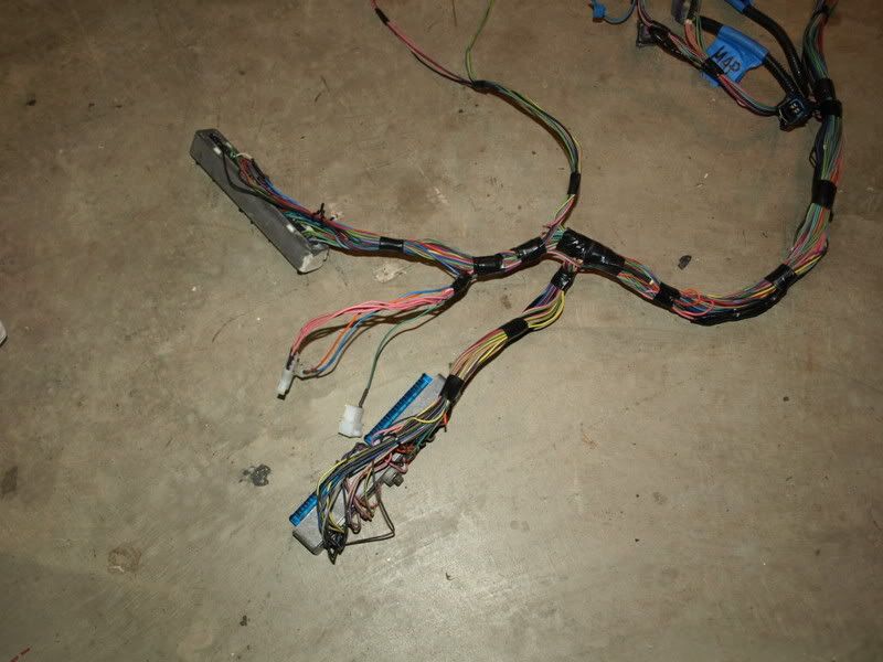
remains of the end of the harness, those 3 white plugs are where it integrates to chassis and tach
fusepanel for engine harness
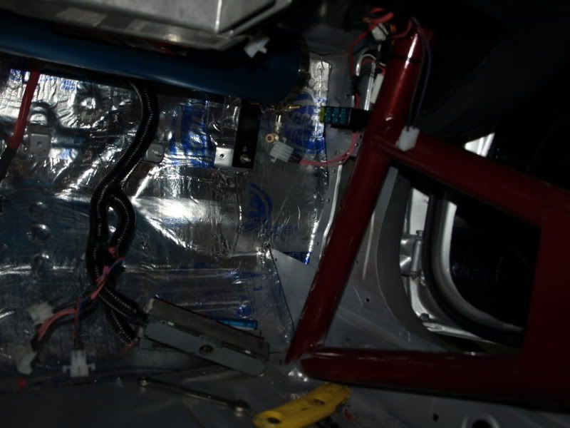
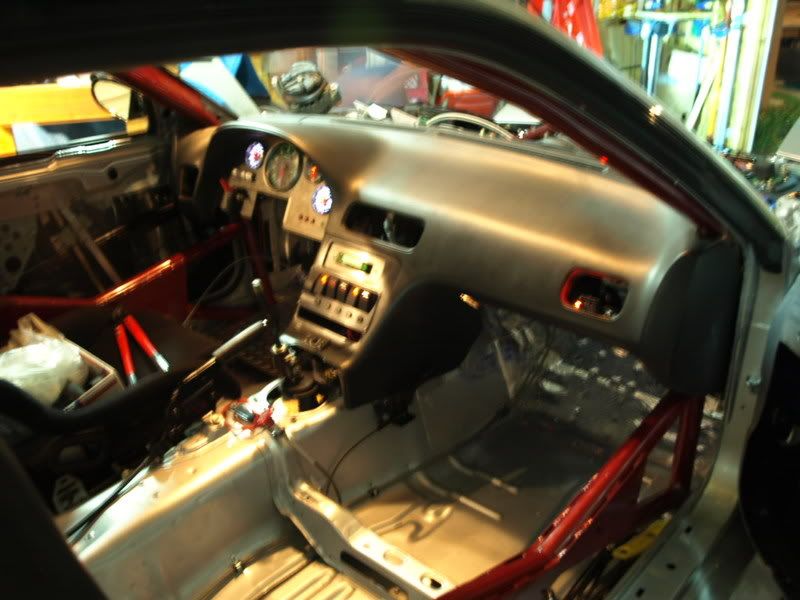
obdII connector in passenger vent
byebye old excess harness
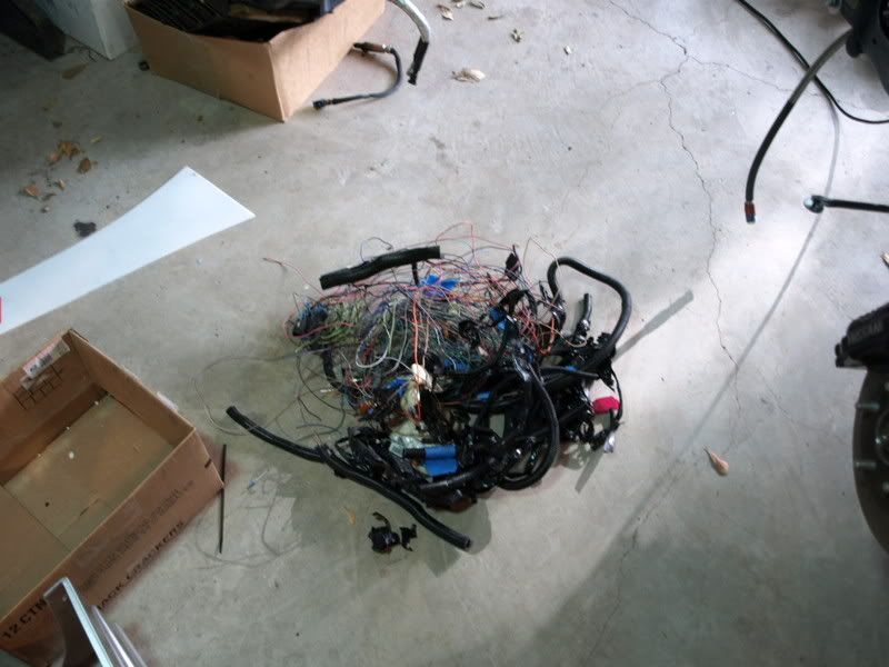
driving soon

thanks calebot, should be unveiling soon!!
remains of the end of the harness, those 3 white plugs are where it integrates to chassis and tach
fusepanel for engine harness
obdII connector in passenger vent
byebye old excess harness
driving soon