
My Engine Committed Suicide Yesterday - RIP


 09-04-2011, 09:10 PM
#242
I forgot about this as this was the night before I left on my trip, but it does count as working on the car.
--------------------------------------------------------------------------
8-2-11
I sold the truck oil pan, windage tray, and pickup tube off of the engine. I had to pull it all off before I went out of town on the 3rd. Here's a few blurry pictures of the bottom end of the engine.


The thing looks incredibly clean and I have no doubt that as advertised the engine has 8k miles. The plans now are to finish the interior parts of the car and order the rest of the engine components to get it ready to drop in.
--------------------------------------------------------------------------
8-2-11
I sold the truck oil pan, windage tray, and pickup tube off of the engine. I had to pull it all off before I went out of town on the 3rd. Here's a few blurry pictures of the bottom end of the engine.
The thing looks incredibly clean and I have no doubt that as advertised the engine has 8k miles. The plans now are to finish the interior parts of the car and order the rest of the engine components to get it ready to drop in.
09-23-2011, 08:14 PM
#243
I got a little motivated last night....
I started by fitting my shift boot and metal ring from Redline Goods. I had to bend the ring a little to get a nice seal around the edges, but I think it looks pretty good.

I hadn't battled with getting the center console in the car in a while so after fighting with it for a long time and getting really sweaty I just decided to dive into the next big project on my list... Removing the cracked dash board and pad.
My dash pad was in great condition when my car blew up, but that was forever ago, and the years of sitting in the sun took their toll. It actually didn't break any more when I went to pull it out.

I'm going to add it and the old dash board to my 93 for sale thread. If the car doesn't ever sell and I get around to putting it back together I'll have about 50% of the parts to do it from the things I've replaced from this car.
Slowly getting there. Getting all of the fasteners out is the easy part, but unplugging all of the wiring, relays, and other electrical connectors attached to the dash is the pain in the ***. When I go to reinstall the new one I'm going to make potential future removals much easier.


This area of wiring was my last snag on getting everything out. I was getting pretty frustrated, but finally got it all out.

Finally free and trying to get it out of the car. I can't open either door of the car more than half way as I have my tool bench on one side and my 93 on the other. It makes things a little difficult.

Finally out of the car.

Here's the extra trim pile. If I ever get around to it I'm going to install the head unit in my 95 as all it has in it now is a non working factory radio / tape player.

A few little oops along the way.


All of this stuff fell out of the dash as I was removing it. Part of them might have been / were me, but I think a couple others were just floating around in there.

Here is my replacement dash board. I need to find one ebony AC vent as one got damaged in shipping. If someone has an extra on feel free to let me know.

Next up on my plate is removing some of the extra wiring in the car that I am no longer going to need, removing the passenger airbag, and trimming the large aluminum brace in the dash. It should be a decent amount of weight and help offset all of the wiring I'm going to add for the gauges, wideband, shift light, and new head unit.
I started by fitting my shift boot and metal ring from Redline Goods. I had to bend the ring a little to get a nice seal around the edges, but I think it looks pretty good.
I hadn't battled with getting the center console in the car in a while so after fighting with it for a long time and getting really sweaty I just decided to dive into the next big project on my list... Removing the cracked dash board and pad.
My dash pad was in great condition when my car blew up, but that was forever ago, and the years of sitting in the sun took their toll. It actually didn't break any more when I went to pull it out.
I'm going to add it and the old dash board to my 93 for sale thread. If the car doesn't ever sell and I get around to putting it back together I'll have about 50% of the parts to do it from the things I've replaced from this car.
Slowly getting there. Getting all of the fasteners out is the easy part, but unplugging all of the wiring, relays, and other electrical connectors attached to the dash is the pain in the ***. When I go to reinstall the new one I'm going to make potential future removals much easier.
This area of wiring was my last snag on getting everything out. I was getting pretty frustrated, but finally got it all out.
Finally free and trying to get it out of the car. I can't open either door of the car more than half way as I have my tool bench on one side and my 93 on the other. It makes things a little difficult.
Finally out of the car.
Here's the extra trim pile. If I ever get around to it I'm going to install the head unit in my 95 as all it has in it now is a non working factory radio / tape player.
A few little oops along the way.
All of this stuff fell out of the dash as I was removing it. Part of them might have been / were me, but I think a couple others were just floating around in there.
Here is my replacement dash board. I need to find one ebony AC vent as one got damaged in shipping. If someone has an extra on feel free to let me know.
Next up on my plate is removing some of the extra wiring in the car that I am no longer going to need, removing the passenger airbag, and trimming the large aluminum brace in the dash. It should be a decent amount of weight and help offset all of the wiring I'm going to add for the gauges, wideband, shift light, and new head unit.
09-25-2011, 12:21 PM
#244
I went into work yesterday morning at 8:00 am and was sent home at 8:47am AKA giant waste of time so... I figured with all of the day ahead of me and nothing to do I should work on my car and knock out as much as I can. It won't look like much, but two things to keep in mind:
1. I work slowly.
2. I am color blind.
My first major task was removing all of the extraneous wiring from the car that a previous owner had added and trimming down the OEM harness slightly. Prepare to be bombarded with pictures as I took quite a few today. My goal for the OEM harness trimming was simply in removing the airbag system and a couple small things that a previous owner had messed with. There were five areas of wiring I had to work on.


I've now trimmed a body harness out of the car, my 93 and still inside of the car with my Formula. I have to say that getting the wiring out of the harness was way easier with it laid out on the floor of my garage, but if I had to really had a choice I would do it in the car. You can see how all of the wires are run, how they connect to things, and pretty much know where they're going to run to. With the harness out of the car you lose that visual reference and the more time you take off from when you removed the harness from the car and start trimming it the worse it gets. Unless you've labeled things ahead of time you'll forget what plugs and have to back track.
With the harness in the car though you'll spend more time unwrapping it and fighting with routing... like I did today.


In working through the harness though I did find myself questioning a couple things. The first is that I noticed this seemed very odd. I'm not sure if this is OEM or not. This plug is located just to the left of the passenger airbag in the dash. It is on the same strand of wires as the light in the glove compartment, a relay, and the light that attaches to the dash pad. What is it and why is it looped like that?


My other point of uncertainty was with this radio plug. The other end of it wasn't hooked to a damn thing and my radio still worked perfectly fine. Was this for an amp or the Bose rear large speaker that mounts on the driver's side where the spare tire area would be?

Here is all of the wiring I managed to remove from the car today:

I'm trying to think of more things I could potentially trim out, but with this car I really want to keep all of the amenities. One area of wiring that I think I could trim a decent amount of weight out of is the OEM amp thing a ma jigger that mounts in the spare tire well. Does anyone have a pin out of that plug? I already pulled four wires out of it today.
The next major step was getting the new dash equally chopped up and ready to go into the car. I pulled sat the new dash next to the one that came out of my car and pulled the passenger airbag out of it first.

After that I flipped it over, pulled the ducting out, and figured out how I was going to hack the dash brace into pieces. I'd read about people trimming it down and knocking about 4.5-5.0 lbs out of the car, but only one person posted pictures and they weren't all that great. Here it is sitting in the dash:

Chop chop:

My next concern was with securing the front of the center console as now the brace that held it to the dash was gone. I decided to chop it down as well so that it'd still mount to the front body mount, but not to the dash brace:


A quick fresh coat of paint to keep it from rusting:

And... Mounted on the dash:


Here is everything that I was able to trim out of the dash, still keep the glove compartment functional, and still have everything mounted securely.

When reinstalling the dash I plan on attaching as little of the wiring harness to the dash and venting as I can. Removing all of the fasteners was easy, but the wiring took easily two to three times longer and was extremely frustrating.
My next steps are to finish reassembling the dash and hopefully getting towards wiring my gauges, shift light, AVIC-D3, and some conversion wiring to do the the PCM swap.
1. I work slowly.
2. I am color blind.
My first major task was removing all of the extraneous wiring from the car that a previous owner had added and trimming down the OEM harness slightly. Prepare to be bombarded with pictures as I took quite a few today. My goal for the OEM harness trimming was simply in removing the airbag system and a couple small things that a previous owner had messed with. There were five areas of wiring I had to work on.
I've now trimmed a body harness out of the car, my 93 and still inside of the car with my Formula. I have to say that getting the wiring out of the harness was way easier with it laid out on the floor of my garage, but if I had to really had a choice I would do it in the car. You can see how all of the wires are run, how they connect to things, and pretty much know where they're going to run to. With the harness out of the car you lose that visual reference and the more time you take off from when you removed the harness from the car and start trimming it the worse it gets. Unless you've labeled things ahead of time you'll forget what plugs and have to back track.
With the harness in the car though you'll spend more time unwrapping it and fighting with routing... like I did today.
In working through the harness though I did find myself questioning a couple things. The first is that I noticed this seemed very odd. I'm not sure if this is OEM or not. This plug is located just to the left of the passenger airbag in the dash. It is on the same strand of wires as the light in the glove compartment, a relay, and the light that attaches to the dash pad. What is it and why is it looped like that?
My other point of uncertainty was with this radio plug. The other end of it wasn't hooked to a damn thing and my radio still worked perfectly fine. Was this for an amp or the Bose rear large speaker that mounts on the driver's side where the spare tire area would be?
Here is all of the wiring I managed to remove from the car today:
I'm trying to think of more things I could potentially trim out, but with this car I really want to keep all of the amenities. One area of wiring that I think I could trim a decent amount of weight out of is the OEM amp thing a ma jigger that mounts in the spare tire well. Does anyone have a pin out of that plug? I already pulled four wires out of it today.
The next major step was getting the new dash equally chopped up and ready to go into the car. I pulled sat the new dash next to the one that came out of my car and pulled the passenger airbag out of it first.
After that I flipped it over, pulled the ducting out, and figured out how I was going to hack the dash brace into pieces. I'd read about people trimming it down and knocking about 4.5-5.0 lbs out of the car, but only one person posted pictures and they weren't all that great. Here it is sitting in the dash:
Chop chop:
My next concern was with securing the front of the center console as now the brace that held it to the dash was gone. I decided to chop it down as well so that it'd still mount to the front body mount, but not to the dash brace:
A quick fresh coat of paint to keep it from rusting:
And... Mounted on the dash:
Here is everything that I was able to trim out of the dash, still keep the glove compartment functional, and still have everything mounted securely.
When reinstalling the dash I plan on attaching as little of the wiring harness to the dash and venting as I can. Removing all of the fasteners was easy, but the wiring took easily two to three times longer and was extremely frustrating.
My next steps are to finish reassembling the dash and hopefully getting towards wiring my gauges, shift light, AVIC-D3, and some conversion wiring to do the the PCM swap.
09-30-2011, 12:42 AM
#245
Ok guys, need to bounce some ideas off of people as I don't really have any help on things. This might sound like a lot of rambling, but I've been doing some research in regards to a lot of electrical wiring for the car. Mostly in regards to installing my electric Autometer gauges: boost, oil, and fuel pressure, LC1 Wideband, DB gauge, and shift light. The amount of information on this site is amazing as otherwise I would have zero means to get things figured out. Reason number 2 I love LS1tech.... While I was typing this my computer gave me the blue screen of death and forced me to restart it. After spending 40+ minutes at that point typing I thought it was going to be lost forever. I fired it back up, recovered my IE tabs, and it was 90% there by some miracle!
I found all of the information for the boost gauge located in a sticky in the forced inductions section: https://ls1tech.com/forums/forced-in...elp-newbs.html
I still had a question though, Question #1: How many items can I pull voltage off of the same 12V switched source? IE, can I hook up every item to the same source or as I'm guessing is there a limit of voltage you can draw from one source?
My next step was finding information on mounting the oil pressure sending unit that Autometer provides with their gauges. I did a couple google searches and found these links: https://ls1tech.com/forums/generatio...auge-help.html
There's a couple pictures of the same installation process in this thread: http://m.modernhemi.com/forums/showthread.php?t=1120231
Which leads to Question #2: What sort of line and fittings do I need to hook this up? I am guessing that I obviously need a 1/8th NPT fitting to plug into the piece above the oil filter, but... what else? Where are you mounting the sending unit once you have it tied into that location?
After figuring out how those two items worked I started to draw some general ideas on how everything works. I did a few quick searches on the fuel pressure sending unit, but found that needed items for installation will vary depending on the fueling setup in the car. While searching I did find a couple very nice links in regards to using the same Autometer fuel pressure sending unit to log fuel pressure. https://ls1tech.com/forums/pcm-diagn...-pressure.html Which leads to --> http://forum.efilive.com/showthread....Pressure-input Which then leads to the detailed installation write up: http://forum.efilive.com/showthread....ure-in-EFILive .
After seeing these variances I thought... Question 3: I plan on running a 10an feed line, 8an return, the fuel rails in parallel, and a boost referenced fuel pressure regulator (BRFPR). With running the rails in parallel where would be the ideal location for the Autometer fuel pressure sending unit?
- Should it be located...
- In the Y feeding the fuel rails?
- Before the BRFPR on one side of the rail?
- Before the regulator but after the rails?
- After the regulator in the Y return fitting?
While searching around I found this link on PT (Post 19). http://www.performancetrucks.net/for...2/#post3923553 This shows the Autometer fuel pressure sending unit right in the feed Y, but it seems he doesn't have a return line.
After having my mind blown by the EFI live forums I started looking in to data logging components (something I know nothing about). Question 4: With EFI live and a laptop in the car how does data logging work and how many inputs can you monitor? Do items like the flashscan V2 only allow tuning and data logging as an alternative to having the laptop in the car? I started looking at the Flashscan V2 and the Innovative DL-32 system, but decided to simply pass it over until I figured out some of the basics.
I'd previously been on here reading about Innovative's LC1 / DB gauge installation woes. After doing some reading and browsing their installation manual I think I have it right? Question 5: Does this sound correct?
Think I have correct...
- The Red wire of the LC1 goes to a switched 12v switched power source with a 5 amp fuse in line.
- The Black wire will have the push button and LED connected to it leaving the single wire now with two ends.
- The Blue, White, and ends of the Black wires get soldered to a single connector which is grounded to the back of a cylinder head only.
With the DB Gauge...
- The Red wire of the gauge goes to 12v switched power source.
- The Black ground wire will connect to the back of the cylinder head with the rest of the LC1's ground wires
- The White wire connects to the LC1's Brown wire
- The Yellow wire connects to the headlight power switch for dimming purposes.
Question #6...
- What can I do with the yellow wire of the LC1 now? It says I can program analog outputs and that it can be used as a narrow band sensor. Where would I run the yellow wire if I was to go that route?
All of the Autometer and the Innovative BD gauges mention in the wiring connecting the gauge to either a switched 12v lighting source or headlight power wire for dimming purposes. With currently having the dash out of the car I decided to check out.

The left connector is for the headlight dimming switch and the one on the right connects to the switch that turns the headlights on. Innovative's directions say not to tie the gauge into the dimming switch in all CAPS, but, "A headlight power wire." Question #7... Which wire is the one that you would tie into for power?
The last one is kind of simple. I was reading the directions for the Raptor shift light I have. I've got everything figured out, but Question #8... I am supposed to tie into the RPM signal for the car. I need some help locating that one.
I've been doing a ton of research on these few things lately as I'm really kind of stuck without getting this stuff done. I haven't bothered with checking out the 24 / 58x conversion box or some of the other things yet as this is my main concern. If anyone has something to add or answer / answers to any / many of the questions I'm all ears. Any help would be grealty appreciated!
Thanks
I found all of the information for the boost gauge located in a sticky in the forced inductions section: https://ls1tech.com/forums/forced-in...elp-newbs.html
I still had a question though, Question #1: How many items can I pull voltage off of the same 12V switched source? IE, can I hook up every item to the same source or as I'm guessing is there a limit of voltage you can draw from one source?
My next step was finding information on mounting the oil pressure sending unit that Autometer provides with their gauges. I did a couple google searches and found these links: https://ls1tech.com/forums/generatio...auge-help.html
There's a couple pictures of the same installation process in this thread: http://m.modernhemi.com/forums/showthread.php?t=1120231
Which leads to Question #2: What sort of line and fittings do I need to hook this up? I am guessing that I obviously need a 1/8th NPT fitting to plug into the piece above the oil filter, but... what else? Where are you mounting the sending unit once you have it tied into that location?
After figuring out how those two items worked I started to draw some general ideas on how everything works. I did a few quick searches on the fuel pressure sending unit, but found that needed items for installation will vary depending on the fueling setup in the car. While searching I did find a couple very nice links in regards to using the same Autometer fuel pressure sending unit to log fuel pressure. https://ls1tech.com/forums/pcm-diagn...-pressure.html Which leads to --> http://forum.efilive.com/showthread....Pressure-input Which then leads to the detailed installation write up: http://forum.efilive.com/showthread....ure-in-EFILive .
After seeing these variances I thought... Question 3: I plan on running a 10an feed line, 8an return, the fuel rails in parallel, and a boost referenced fuel pressure regulator (BRFPR). With running the rails in parallel where would be the ideal location for the Autometer fuel pressure sending unit?
- Should it be located...
- In the Y feeding the fuel rails?
- Before the BRFPR on one side of the rail?
- Before the regulator but after the rails?
- After the regulator in the Y return fitting?
While searching around I found this link on PT (Post 19). http://www.performancetrucks.net/for...2/#post3923553 This shows the Autometer fuel pressure sending unit right in the feed Y, but it seems he doesn't have a return line.
After having my mind blown by the EFI live forums I started looking in to data logging components (something I know nothing about). Question 4: With EFI live and a laptop in the car how does data logging work and how many inputs can you monitor? Do items like the flashscan V2 only allow tuning and data logging as an alternative to having the laptop in the car? I started looking at the Flashscan V2 and the Innovative DL-32 system, but decided to simply pass it over until I figured out some of the basics.
I'd previously been on here reading about Innovative's LC1 / DB gauge installation woes. After doing some reading and browsing their installation manual I think I have it right? Question 5: Does this sound correct?
Think I have correct...
- The Red wire of the LC1 goes to a switched 12v switched power source with a 5 amp fuse in line.
- The Black wire will have the push button and LED connected to it leaving the single wire now with two ends.
- The Blue, White, and ends of the Black wires get soldered to a single connector which is grounded to the back of a cylinder head only.
With the DB Gauge...
- The Red wire of the gauge goes to 12v switched power source.
- The Black ground wire will connect to the back of the cylinder head with the rest of the LC1's ground wires
- The White wire connects to the LC1's Brown wire
- The Yellow wire connects to the headlight power switch for dimming purposes.
Question #6...
- What can I do with the yellow wire of the LC1 now? It says I can program analog outputs and that it can be used as a narrow band sensor. Where would I run the yellow wire if I was to go that route?
All of the Autometer and the Innovative BD gauges mention in the wiring connecting the gauge to either a switched 12v lighting source or headlight power wire for dimming purposes. With currently having the dash out of the car I decided to check out.
The left connector is for the headlight dimming switch and the one on the right connects to the switch that turns the headlights on. Innovative's directions say not to tie the gauge into the dimming switch in all CAPS, but, "A headlight power wire." Question #7... Which wire is the one that you would tie into for power?
The last one is kind of simple. I was reading the directions for the Raptor shift light I have. I've got everything figured out, but Question #8... I am supposed to tie into the RPM signal for the car. I need some help locating that one.
I've been doing a ton of research on these few things lately as I'm really kind of stuck without getting this stuff done. I haven't bothered with checking out the 24 / 58x conversion box or some of the other things yet as this is my main concern. If anyone has something to add or answer / answers to any / many of the questions I'm all ears. Any help would be grealty appreciated!
Thanks
10-02-2011, 11:19 PM
#247
I've managed to answer a few of my questions so far through doing a lot of research. I thought I would post the answers for anyone that may potentially have the same questions later on.
--------------------------------------------------------------------------
From my 9-25-11 Post: https://ls1tech.com/forums/15431962-post383.html
Questions Answered:
Question: Was this (plug on the back of the OEM Monsoon cd player) for an amp or the Bose rear large speaker that mounts on the driver's side where the spare tire area would be?
Answer: That plug is for the OEM CD changer. Even if your car is not equiped with a CD changer the wiring will still be inside of the car. It will look like this: http://i395.photobucket.com/albums/p...g/PA010010.jpg
Question: Does anyone have a pin out of that (OEM amp located in the spare tire area) plug?
Answer: https://ls1tech.com/forums/5962246-post5.html Located in this post / sticky: https://ls1tech.com/forums/stereo-el...nsoon-faq.html
Question Still Unanswered:
Question 1: In working through the harness though I did find myself questioning a couple things. The first is that I noticed this seemed very odd. I'm not sure if this is OEM or not. This plug is located just to the left of the passenger airbag in the dash. It is on the same strand of wires as the light in the glove compartment, a relay, and the light that attaches to the dash pad. What is it and why is it looped like that?
Pictures of said wiring:
http://64.19.142.13/i395.photobucket...g/P9230010.jpg
http://64.19.142.10/i395.photobucket...g/P9230011.jpg
--------------------------------------------------------------------------
From my 9-30-11 Post: https://ls1tech.com/forums/15451543-post386.html
Questions Answered:
Question: I plan on running a 10an feed line, 8an return, the fuel rails in parallel, and a boost referenced fuel pressure regulator (BRFPR). With running the rails in parallel where would be the ideal location for the Autometer fuel pressure sending unit?
Answer: Question: In installing my Raptor shift light I am supposed to tie into the RPM signal for the car. I need some help locating that one.
Answer: Full installation information: https://ls1tech.com/forums/stereo-el...-tap-into.html
Awesome link for pretty much any car: https://ls1tech.com/forums/3844437-post54.html
Questions Still Unaswered:
Question 2: How many items can I pull voltage off of the same 12V switched source? IE, can I hook up every item to the same source or as I'm guessing is there a limit of voltage you can draw from one source?
Question 3: In installing my Autometer electric oil pressure sending unit in the OEM block off above the oil pan what sort of line and fittings do I need? I am guessing that I obviously need a 1/8th NPT fitting to plug into the piece above the oil filter, but... what else? Where are you mounting the sending unit once you have it tied into that location? Visual example: http://m.modernhemi.com/forums/showthread.php?t=1120231
Question 4: With EFI live and a laptop in the car how does data logging work and how many inputs can you monitor? Do items like the flashscan V2 only allow tuning and data logging as an alternative to having the laptop in the car? Has anyone tried an ELM327 interface for data logging? I found a little information here:
https://ls1tech.com/forums/pcm-diagn...-software.html
https://ls1tech.com/forums/pcm-diagn...are-other.html
https://ls1tech.com/forums/cadillac-...oid-phone.html
Question 5: In connecting my LC1 wideband and DB gauge does this sound correct?
Think I have correct...
- The Red wire of the LC1 goes to a switched 12v switched power source with a 5 amp fuse in line.
- The Black wire will have the push button and LED connected to it leaving the single wire now with two ends.
- The Blue, White, and ends of the Black wires get soldered to a single connector which is grounded to the back of a cylinder head only.
With the DB Gauge...
- The Red wire of the gauge goes to 12v switched power source.
- The Black ground wire will connect to the back of the cylinder head with the rest of the LC1's ground wires
- The White wire connects to the LC1's Brown wire
- The Yellow wire connects to the headlight power switch for dimming purposes.
Question #6: What can I do with the yellow wire of the LC1 now? It says I can program analog outputs and that it can be used as a narrow band sensor. Where would I run the yellow wire if I was to go that route?
Question #7: Which wire is the switched 12v lighting source or headlight power wire for dimming purposes that you would tie into for an LC1 or Autometer gauge? Visual reference: http://64.19.142.12/i395.photobucket...g/P9290004.jpg
--------------------------------------------------------------------------
All of my recent efforts have been in regards to wiring and I'm slowly figuring things out. I went through the Monsoon sticky and used the wiring diagram of the factory amp to figure out the wires that I had removed were:
F13 - GRAY - right rear midrange speaker negative output
F14 - WHITE - right rear midrange speaker positive output
F15 - RED - left rear midrange speaker positive output
F16 - PURPLE - left rear midrange speaker negative output
My car only has four speakers in it and I plan on keeping it that way so it worked out.
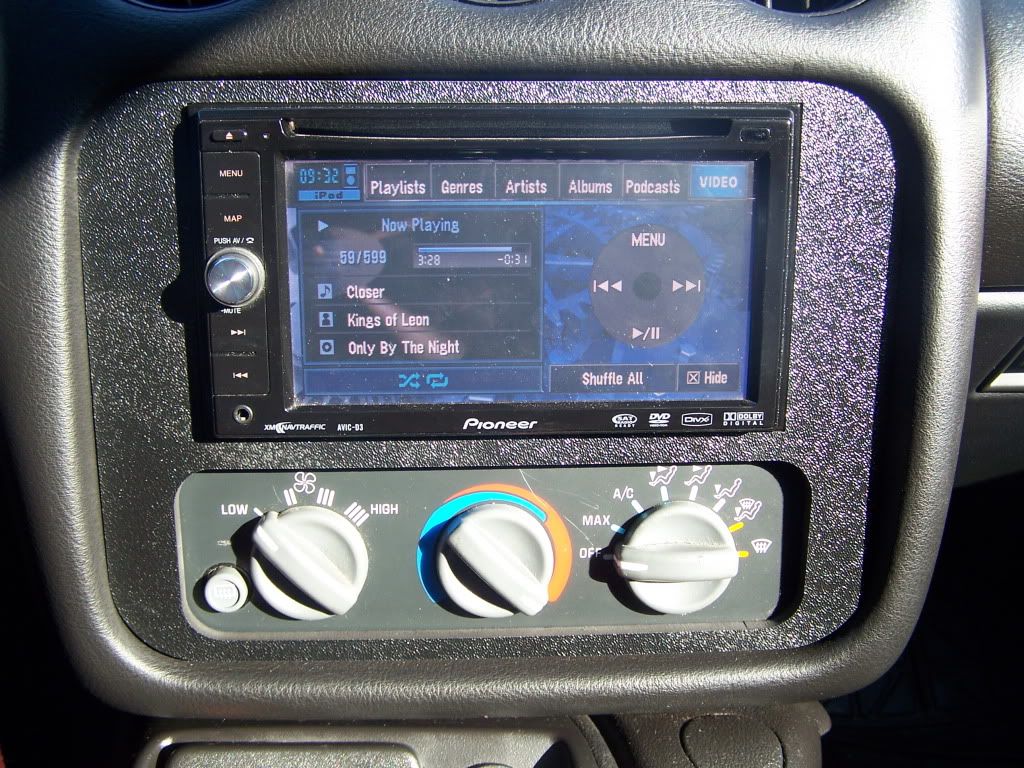
I started looking into what all was needed for installing my Pioneer AVIC-D3 head unit and related wiring. The Monsoon sticky and related link: https://ls1tech.com/forums/stereo-el...installed.html are a good source of information, but the wiring still has me confused. I have all of this to get into the car:

I have the Ipod cable, bluetooth module, and GPS antenna figured out. I just am kind of confused in regards to the other wiring that needs to be tied into the car. There are a white and a black plug that connect into the back of the head unit and I have no idea how the wiring of those connectors needs to be run. I'm going to try and contact the member that I purchased it from, if that fails download the user manual, and start reading.
Again if anyone has answers to any of these questions I'd love to hear them.
--------------------------------------------------------------------------
From my 9-25-11 Post: https://ls1tech.com/forums/15431962-post383.html
Questions Answered:
Question: Was this (plug on the back of the OEM Monsoon cd player) for an amp or the Bose rear large speaker that mounts on the driver's side where the spare tire area would be?
Answer: That plug is for the OEM CD changer. Even if your car is not equiped with a CD changer the wiring will still be inside of the car. It will look like this: http://i395.photobucket.com/albums/p...g/PA010010.jpg
Question: Does anyone have a pin out of that (OEM amp located in the spare tire area) plug?
Answer: https://ls1tech.com/forums/5962246-post5.html Located in this post / sticky: https://ls1tech.com/forums/stereo-el...nsoon-faq.html
Question Still Unanswered:
Question 1: In working through the harness though I did find myself questioning a couple things. The first is that I noticed this seemed very odd. I'm not sure if this is OEM or not. This plug is located just to the left of the passenger airbag in the dash. It is on the same strand of wires as the light in the glove compartment, a relay, and the light that attaches to the dash pad. What is it and why is it looped like that?
Pictures of said wiring:
http://64.19.142.13/i395.photobucket...g/P9230010.jpg
http://64.19.142.10/i395.photobucket...g/P9230011.jpg
--------------------------------------------------------------------------
From my 9-30-11 Post: https://ls1tech.com/forums/15451543-post386.html
Questions Answered:
Question: I plan on running a 10an feed line, 8an return, the fuel rails in parallel, and a boost referenced fuel pressure regulator (BRFPR). With running the rails in parallel where would be the ideal location for the Autometer fuel pressure sending unit?
Answer:
The regulator goes post feed. So if you fed them both in parallel from the rear, the front of the rails would have to go to the regulator and then the bottom return goes to the tank. The sending unit will go in the fuel pressure regulator. There's an 1/8npt port on it, and that's what it's used for.
Answer: Full installation information: https://ls1tech.com/forums/stereo-el...-tap-into.html
Awesome link for pretty much any car: https://ls1tech.com/forums/3844437-post54.html
Questions Still Unaswered:
Question 2: How many items can I pull voltage off of the same 12V switched source? IE, can I hook up every item to the same source or as I'm guessing is there a limit of voltage you can draw from one source?
Question 3: In installing my Autometer electric oil pressure sending unit in the OEM block off above the oil pan what sort of line and fittings do I need? I am guessing that I obviously need a 1/8th NPT fitting to plug into the piece above the oil filter, but... what else? Where are you mounting the sending unit once you have it tied into that location? Visual example: http://m.modernhemi.com/forums/showthread.php?t=1120231
Question 4: With EFI live and a laptop in the car how does data logging work and how many inputs can you monitor? Do items like the flashscan V2 only allow tuning and data logging as an alternative to having the laptop in the car? Has anyone tried an ELM327 interface for data logging? I found a little information here:
https://ls1tech.com/forums/pcm-diagn...-software.html
https://ls1tech.com/forums/pcm-diagn...are-other.html
https://ls1tech.com/forums/cadillac-...oid-phone.html
Question 5: In connecting my LC1 wideband and DB gauge does this sound correct?
Think I have correct...
- The Red wire of the LC1 goes to a switched 12v switched power source with a 5 amp fuse in line.
- The Black wire will have the push button and LED connected to it leaving the single wire now with two ends.
- The Blue, White, and ends of the Black wires get soldered to a single connector which is grounded to the back of a cylinder head only.
With the DB Gauge...
- The Red wire of the gauge goes to 12v switched power source.
- The Black ground wire will connect to the back of the cylinder head with the rest of the LC1's ground wires
- The White wire connects to the LC1's Brown wire
- The Yellow wire connects to the headlight power switch for dimming purposes.
Question #6: What can I do with the yellow wire of the LC1 now? It says I can program analog outputs and that it can be used as a narrow band sensor. Where would I run the yellow wire if I was to go that route?
Question #7: Which wire is the switched 12v lighting source or headlight power wire for dimming purposes that you would tie into for an LC1 or Autometer gauge? Visual reference: http://64.19.142.12/i395.photobucket...g/P9290004.jpg
--------------------------------------------------------------------------
All of my recent efforts have been in regards to wiring and I'm slowly figuring things out. I went through the Monsoon sticky and used the wiring diagram of the factory amp to figure out the wires that I had removed were:
F13 - GRAY - right rear midrange speaker negative output
F14 - WHITE - right rear midrange speaker positive output
F15 - RED - left rear midrange speaker positive output
F16 - PURPLE - left rear midrange speaker negative output
My car only has four speakers in it and I plan on keeping it that way so it worked out.
I started looking into what all was needed for installing my Pioneer AVIC-D3 head unit and related wiring. The Monsoon sticky and related link: https://ls1tech.com/forums/stereo-el...installed.html are a good source of information, but the wiring still has me confused. I have all of this to get into the car:
I have the Ipod cable, bluetooth module, and GPS antenna figured out. I just am kind of confused in regards to the other wiring that needs to be tied into the car. There are a white and a black plug that connect into the back of the head unit and I have no idea how the wiring of those connectors needs to be run. I'm going to try and contact the member that I purchased it from, if that fails download the user manual, and start reading.
Again if anyone has answers to any of these questions I'd love to hear them.
10-03-2011, 02:45 PM
#248
I REALLY need some help guys. I plugged in the gauge cluster and reconnected the grounds so I could put voltage to the car. I was attempting to check for 12v sources and the switched lighting source, but... Every time I connect the positive terminal of my battery the horn will honk continuously. I cannot get it to turn off unless I disconnect the positive terminal of the battery. I tried pulling the airbag to see if the horn leads were messed up... they weren't. I then disconnected the plug for the horn under the steering column and it is still going off. Could this have anything to do with the airbag wiring being removed from the car? As in the car thinks the airbags went off and is honking the horn?
I REALLY need help with this guys as this is completely derailing me working on the car right now. I have tons of alcohol and will buy a sub for anyone that can come over to help me figure this out.
I REALLY need help with this guys as this is completely derailing me working on the car right now. I have tons of alcohol and will buy a sub for anyone that can come over to help me figure this out.
 10-03-2011, 06:21 PM
#250
It ended up being the horn relay. I sent a text to a friend of mine and he called it right off the bat. My fuses are mounted down in front of the driver's front tire. When I cut the hole to put them down there I made it too small to pull the panels back through there without MAJOR disconnecting, removing the front wheel, other things, and a general pain in the ***. I pulled the relay for the fog lights and stuck it in there for now and no more honking! I'm going to go pick up a new relay and some fuses for my gauges here in a little bit before Advanced Discount Auto closes. Then, cut a WAY larger hole for my fuse boxes to come through.
Thanks for the quick replies guys. You have no idea how annoying it is to have your car not stop honking at you.
He also told me I can hook my gauges up to one switched power source. I'll have pictures and details later. I'm going to try and salvage today despite the major time spent on trying to figure the honking issue out.
10-04-2011, 11:00 PM
#251
I started yesterday with all of these great ideas on getting stuff done. With the help of LS1tech members and google searching for things on the site I'd found quite a few things I was looking for. Thanks guys  and
and  ! My plan was to install the wiring for my gauges, shift light, and work on my battery cutoff wiring.

I started off by fixing a ground wire that I had broken when removing the dash. Obviously, I didn't get all of the wires off of the dash like I thought I had. It is honestly a giant pain in the *** to get the wiring off of it.

Fixed:

With that fixed I attached it to the body as a temporary ground. I stuck the gauge cluster in the car, attached the rest of the grounds, and some other connectors.

My plan was to break out my multi meter and measure some wires to find switched 12v power sources and switched lighting sources. I had my old battery in the car which is almost dead, but holds about 35% of a charge. It is enough to get some slight testing done, but after a few days of use it will go dead. When, I went to connect the battery cables it was of course dead. I then stuck my new red top in the car so I could get all of my testing done and that's when all hell broke loose.
I had the negative connected to the battery and went to wedge my positive against the terminal. My positive has a ring end on it to connect to my cutoff switch so I have to wedge it against the terminal with the handle of the battery. As soon as I touched it to the positive post my horn honked. I thought, "Wow, that's odd. I wonder if that was just some odd one time deal? Let's try it again." - Touches cable to post again... HHHOOOONNNKKKK! I did this a few times to make sure I wasn't going crazy and every time I touched it to the post it started honking and wouldn't stop. I couldn't get it to shut off as long as I had it connected to the positive post.
I started by checking to see if something beneath the airbag was stuck or the wiring was damaged. It all checked out and as soon as I attempted to reconnect the positive cable more steady honking. I pulled the passenger head light up real quick with my impact and checked out the horn. With all of the headlight wiring and the new bracket maybe something was out of whack, but it checked out as well. I started doing some research, but couldn't figure out what it was. I sent out a couple emails and a few texts to see if anyone knew and the only person who responded told me to check the horn relay located on the driver's side under the hood. Well, if anyone remembers I relocated mine beneath the car so it was going to be a little more complicated to check it out, but I figured why not. Let's start simple before I start going insane trying to figure out if I messed something up with my conversion wiring, removing interior wiring, or something else.
The first thing on my list of things to do was pull the cover I made for the fuse area off. Which, is normally super easy... Keyword, normally. It just has one large bolt with a wing nut on one side and a self tapping screw in the frame on the other. The wing nut and bolt came off super easy, but when I went to remove the self tapping screw the head broke off leaving the rest of it threaded in my cover mount and the body, leaving them stuck together. I ended up taking a hammer and beating the crap out of the screw to get
the mount to come away from the body. Even at this point in time the end of the screw is still stuck in the body. I need to figure out something in regards to replacing it.

Once I finally got that off I tried to simply pull the fuse boxes up back throuh the hole. It most definetely was not going to happen. I had the ABS block connector, firebird headlight switches, HID wiring, passenger window motor wiring, and other things all jammed down that same hole as well. Earlier in the day I had let my friend borrow my jack so he could work on his van (77 short box - 383 / 700r4). Thinking I was only going to be working on wiring I didn't foresee any issues with this. DOT! I ended up taking the GM scissor jack out of my 95 Camaro DD, using 4 extensions on my impact, and jacking the car up with that enough to get the wheel off. (This is once I got it fixed)

* When you're planning on doing something to your car think about how it is going to potentially affect you working on your car in the future*
When I made the cut for the fuse boxes to go through I didn't make it that large. When, I added the weather stripping around the edge and all of the other wiring it just added to the problem of the hole being too small and made it next to impossible to get the fuse boxes out. With the wheel off, the rest of the wiring pulled off of the power post, and some odd sitting positions I would have been able to check the relay, but I wanted to do things the right way and fix the added problem of inadequate space. In the future I didn't want to blow a fuse and be stuck on the side of the road trying to pull the inner fender, a wheel off, and laying on my back to check for problems. After about an hour and a half of removing all removing all of the other wiring I had added, the headlight motor wiring, and trying a million ways of forcing the fuse boxes out of the hole with one hand pushing from the bottom and the other from the pushing the other box to the side one finally came out! With one out the other one was way easier and I was stoked.

* Do NOT ever cut your hole like this! *
With the boxes finally out I pulled the cover off and located the horn relay. I found that the fog light relay (I believe) is right next to it. I pulled the horn relay out, stuck the one from the fog lights in its place, and connected the positive battery cable to the post. Silence, no more honking! It was so simple, but in not knowing what to do and then having pretty much everything possible go wrong it ended up taking me around 3 hours from when it started honking to silence.
In short... If your horn ever gets stuck on check the horn relay as it may be stuck open.
I'll post today's work when I get home tomorrow. I have to get up in 5 hours.
and ! My plan was to install the wiring for my gauges, shift light, and work on my battery cutoff wiring.I started off by fixing a ground wire that I had broken when removing the dash. Obviously, I didn't get all of the wires off of the dash like I thought I had. It is honestly a giant pain in the *** to get the wiring off of it.
Fixed:
With that fixed I attached it to the body as a temporary ground. I stuck the gauge cluster in the car, attached the rest of the grounds, and some other connectors.
My plan was to break out my multi meter and measure some wires to find switched 12v power sources and switched lighting sources. I had my old battery in the car which is almost dead, but holds about 35% of a charge. It is enough to get some slight testing done, but after a few days of use it will go dead. When, I went to connect the battery cables it was of course dead. I then stuck my new red top in the car so I could get all of my testing done and that's when all hell broke loose.
I had the negative connected to the battery and went to wedge my positive against the terminal. My positive has a ring end on it to connect to my cutoff switch so I have to wedge it against the terminal with the handle of the battery. As soon as I touched it to the positive post my horn honked. I thought, "Wow, that's odd. I wonder if that was just some odd one time deal? Let's try it again." - Touches cable to post again... HHHOOOONNNKKKK! I did this a few times to make sure I wasn't going crazy and every time I touched it to the post it started honking and wouldn't stop. I couldn't get it to shut off as long as I had it connected to the positive post.
I started by checking to see if something beneath the airbag was stuck or the wiring was damaged. It all checked out and as soon as I attempted to reconnect the positive cable more steady honking. I pulled the passenger head light up real quick with my impact and checked out the horn. With all of the headlight wiring and the new bracket maybe something was out of whack, but it checked out as well. I started doing some research, but couldn't figure out what it was. I sent out a couple emails and a few texts to see if anyone knew and the only person who responded told me to check the horn relay located on the driver's side under the hood. Well, if anyone remembers I relocated mine beneath the car so it was going to be a little more complicated to check it out, but I figured why not. Let's start simple before I start going insane trying to figure out if I messed something up with my conversion wiring, removing interior wiring, or something else.
The first thing on my list of things to do was pull the cover I made for the fuse area off. Which, is normally super easy... Keyword, normally. It just has one large bolt with a wing nut on one side and a self tapping screw in the frame on the other. The wing nut and bolt came off super easy, but when I went to remove the self tapping screw the head broke off leaving the rest of it threaded in my cover mount and the body, leaving them stuck together. I ended up taking a hammer and beating the crap out of the screw to get
the mount to come away from the body. Even at this point in time the end of the screw is still stuck in the body. I need to figure out something in regards to replacing it.
Once I finally got that off I tried to simply pull the fuse boxes up back throuh the hole. It most definetely was not going to happen. I had the ABS block connector, firebird headlight switches, HID wiring, passenger window motor wiring, and other things all jammed down that same hole as well. Earlier in the day I had let my friend borrow my jack so he could work on his van (77 short box - 383 / 700r4). Thinking I was only going to be working on wiring I didn't foresee any issues with this. DOT! I ended up taking the GM scissor jack out of my 95 Camaro DD, using 4 extensions on my impact, and jacking the car up with that enough to get the wheel off. (This is once I got it fixed)
* When you're planning on doing something to your car think about how it is going to potentially affect you working on your car in the future*
When I made the cut for the fuse boxes to go through I didn't make it that large. When, I added the weather stripping around the edge and all of the other wiring it just added to the problem of the hole being too small and made it next to impossible to get the fuse boxes out. With the wheel off, the rest of the wiring pulled off of the power post, and some odd sitting positions I would have been able to check the relay, but I wanted to do things the right way and fix the added problem of inadequate space. In the future I didn't want to blow a fuse and be stuck on the side of the road trying to pull the inner fender, a wheel off, and laying on my back to check for problems. After about an hour and a half of removing all removing all of the other wiring I had added, the headlight motor wiring, and trying a million ways of forcing the fuse boxes out of the hole with one hand pushing from the bottom and the other from the pushing the other box to the side one finally came out! With one out the other one was way easier and I was stoked.
* Do NOT ever cut your hole like this! *
With the boxes finally out I pulled the cover off and located the horn relay. I found that the fog light relay (I believe) is right next to it. I pulled the horn relay out, stuck the one from the fog lights in its place, and connected the positive battery cable to the post. Silence, no more honking! It was so simple, but in not knowing what to do and then having pretty much everything possible go wrong it ended up taking me around 3 hours from when it started honking to silence.
In short... If your horn ever gets stuck on check the horn relay as it may be stuck open.
I'll post today's work when I get home tomorrow. I have to get up in 5 hours.
10-05-2011, 07:47 PM
#252
Monday, night I made a last ditch minute effort to make it into Advanced Discount Auto and picked up a new horn relay, some fuses, and a couple odds and ends. When I got up yesterday I went straight down to the garage, started working on the car, and trying to help my friend finish his van. My first task was fixing my previous issues with my fuse panel relocation. Here is what the previous hole looked like with the old weather stripping in it.

Cut:

Finished with some 3/16ths windshield fluid hose with a slit down the side.

I jammed all of the fuse panels back in and this is what it will looks like with everything just sitting there.

When I drilled one of the new holes for a zip tie I used a drill bit in my impact. Don't ever do this. It got twisted in the impact and was a bitch to get out.

I started doing some google searches and trying to trace some wires for mounting my gauges, shift light, conversion wiring, etc... I managed to answer a ton of my earlier questions. I'll keep this post updated as best as I can so if anyone is ever trying to find some of this information they can.
Post beneath this one.
Cut:
Finished with some 3/16ths windshield fluid hose with a slit down the side.
I jammed all of the fuse panels back in and this is what it will looks like with everything just sitting there.
When I drilled one of the new holes for a zip tie I used a drill bit in my impact. Don't ever do this. It got twisted in the impact and was a bitch to get out.
I started doing some google searches and trying to trace some wires for mounting my gauges, shift light, conversion wiring, etc... I managed to answer a ton of my earlier questions. I'll keep this post updated as best as I can so if anyone is ever trying to find some of this information they can.
Post beneath this one.
10-05-2011, 08:15 PM
#253
I've managed to answer a few of my questions so far through doing a lot of research. I thought I would post the answers for anyone that may potentially have the same questions later on.
--------------------------------------------------------------------------
From my 9-25-11 Post: https://ls1tech.com/forums/15431962-post383.html
Questions Answered:
Question: Was this (plug on the back of the OEM Monsoon cd player) for an amp or the Bose rear large speaker that mounts on the driver's side where the spare tire area would be?
Answer: That plug is for the OEM CD changer. Even if your car is not equiped with a CD changer the wiring will still be inside of the car. It will look like this: http://i395.photobucket.com/albums/p...g/PA010010.jpg
Question: Does anyone have a pin out of that (OEM amp located in the spare tire area) plug?
Answer: https://ls1tech.com/forums/5962246-post5.html Located in this post / sticky: https://ls1tech.com/forums/stereo-el...nsoon-faq.html
Question Still Unanswered:
Question 1: In working through the harness though I did find myself questioning a couple things. The first is that I noticed this seemed very odd. I'm not sure if this is OEM or not. This plug is located just to the left of the passenger airbag in the dash. It is on the same strand of wires as the light in the glove compartment, a relay, and the light that attaches to the dash pad. What is it and why is it looped like that?
Pictures of said wiring:
http://64.19.142.13/i395.photobucket...g/P9230010.jpg
http://64.19.142.10/i395.photobucket...g/P9230011.jpg
--------------------------------------------------------------------------
From my 9-30-11 Post: https://ls1tech.com/forums/15451543-post386.html
Questions Answered:
Question: I plan on running a 10an feed line, 8an return, the fuel rails in parallel, and a boost referenced fuel pressure regulator (BRFPR). With running the rails in parallel where would be the ideal location for the Autometer fuel pressure sending unit?
Answer: Question: In installing my Raptor shift light I am supposed to tie into the RPM signal for the car. I need some help locating that one.
Answer: Full installation information: https://ls1tech.com/forums/stereo-el...-tap-into.html
Awesome link for pretty much any car: https://ls1tech.com/forums/3844437-post54.html
Question 2: How many items can I pull voltage off of the same 12V switched source? IE, can I hook up every item to the same source or as I'm guessing is there a limit of voltage you can draw from one source?
Question #7: Which wire is the switched 12v lighting source or headlight power wire for dimming purposes that you would tie into for an LC1 or Autometer gauge? Visual reference: http://64.19.142.12/i395.photobucket...g/P9290004.jpg
Answer for #2 and #7: https://ls1tech.com/forums/stereo-el...2-12v-key.html
Question 3: In installing my Autometer electric oil pressure sending unit in the OEM block off above the oil pan what sort of line and fittings do I need? I am guessing that I obviously need a 1/8th NPT fitting to plug into the piece above the oil filter, but... what else? Where are you mounting the sending unit once you have it tied into that location? Visual example: http://m.modernhemi.com/forums/showthread.php?t=1120231
Answer: For the line I'd use a 3an ish line with 1/8th NPT female fittings on both sides. I'm still not sure on mounting, but I think you could tuck it up behind the intake manifold.
--------------------------------------------------------------------------
--------------------------------------------------------------------------
From my 9-25-11 Post: https://ls1tech.com/forums/15431962-post383.html
Questions Answered:
Question: Was this (plug on the back of the OEM Monsoon cd player) for an amp or the Bose rear large speaker that mounts on the driver's side where the spare tire area would be?
Answer: That plug is for the OEM CD changer. Even if your car is not equiped with a CD changer the wiring will still be inside of the car. It will look like this: http://i395.photobucket.com/albums/p...g/PA010010.jpg
Question: Does anyone have a pin out of that (OEM amp located in the spare tire area) plug?
Answer: https://ls1tech.com/forums/5962246-post5.html Located in this post / sticky: https://ls1tech.com/forums/stereo-el...nsoon-faq.html
Question Still Unanswered:
Question 1: In working through the harness though I did find myself questioning a couple things. The first is that I noticed this seemed very odd. I'm not sure if this is OEM or not. This plug is located just to the left of the passenger airbag in the dash. It is on the same strand of wires as the light in the glove compartment, a relay, and the light that attaches to the dash pad. What is it and why is it looped like that?
Pictures of said wiring:
http://64.19.142.13/i395.photobucket...g/P9230010.jpg
http://64.19.142.10/i395.photobucket...g/P9230011.jpg
--------------------------------------------------------------------------
From my 9-30-11 Post: https://ls1tech.com/forums/15451543-post386.html
Questions Answered:
Question: I plan on running a 10an feed line, 8an return, the fuel rails in parallel, and a boost referenced fuel pressure regulator (BRFPR). With running the rails in parallel where would be the ideal location for the Autometer fuel pressure sending unit?
Answer:
The regulator goes post feed. So if you fed them both in parallel from the rear, the front of the rails would have to go to the regulator and then the bottom return goes to the tank. The sending unit will go in the fuel pressure regulator. There's an 1/8npt port on it, and that's what it's used for.
Answer: Full installation information: https://ls1tech.com/forums/stereo-el...-tap-into.html
Awesome link for pretty much any car: https://ls1tech.com/forums/3844437-post54.html
Question 2: How many items can I pull voltage off of the same 12V switched source? IE, can I hook up every item to the same source or as I'm guessing is there a limit of voltage you can draw from one source?
Question #7: Which wire is the switched 12v lighting source or headlight power wire for dimming purposes that you would tie into for an LC1 or Autometer gauge? Visual reference: http://64.19.142.12/i395.photobucket...g/P9290004.jpg
Answer for #2 and #7: https://ls1tech.com/forums/stereo-el...2-12v-key.html
This was covered a few posts down from here:
https://ls1tech.com/forums/stereo-el...ce-gauges.html
Driver's side fuse panel (interior):
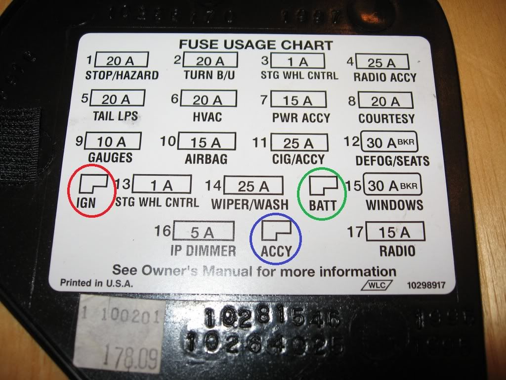
Red Circle = IGN = Switched 12V Power (has power when key is in the on position, but does not have power otherwise)
Green Circle = BATT = 12V Always Hot (has power regardless of key position)
Blue Circle = ACCY = 12V Retained Accessory Power (best example is the radio - this will energize when the car is turned on, and will stay powered even after the car is turned off, but will turn off once the door is opened)
These slots can be accessed by using a flat blade connector crimped on the end of a wire (then use the wire to power whatever you wish) - just shove the connector in the appropriate slot from the front of the panel.
https://ls1tech.com/forums/stereo-el...ce-gauges.html
Driver's side fuse panel (interior):
Red Circle = IGN = Switched 12V Power (has power when key is in the on position, but does not have power otherwise)
Green Circle = BATT = 12V Always Hot (has power regardless of key position)
Blue Circle = ACCY = 12V Retained Accessory Power (best example is the radio - this will energize when the car is turned on, and will stay powered even after the car is turned off, but will turn off once the door is opened)
These slots can be accessed by using a flat blade connector crimped on the end of a wire (then use the wire to power whatever you wish) - just shove the connector in the appropriate slot from the front of the panel.
Answer: For the line I'd use a 3an ish line with 1/8th NPT female fittings on both sides. I'm still not sure on mounting, but I think you could tuck it up behind the intake manifold.
Question 4: With EFI live and a laptop in the car how does data logging work and how many inputs can you monitor? Do items like the flashscan V2 only allow tuning and data logging as an alternative to having the laptop in the car? Has anyone tried an ELM327 interface for data logging? I found a little information here:
You can log I believe 32 PID's at one time, although the more you do, the slower and less resolution you get.. There are 4 external 5v inputs that you can use for anything, 2 temperature inputs, and two 12v switched inputs. I haven't figured out black box logging, but you supposedly select PID's, (8 or so) and you can log them onto a standard SD card for review later. You can also flash tunes from your handlheld without a laptop, or use it passthru. I use my laptop because I like to see the PID list. (small screen on unit)
Diagnostic/datalogging software?
Data Logging - Problem with hardware/software/other?
If anyone has an android phone...
Question 5: In connecting my LC1 wideband and DB gauge does this sound correct?
Think I have correct...
- The Red wire of the LC1 goes to a switched 12v switched power source with a 5 amp fuse in line.
- The Black wire will have the push button and LED connected to it leaving the single wire now with two ends.
- The Blue, White, and ends of the Black wires get soldered to a single connector which is grounded to the back of a cylinder head only.
I'll get back to you on that one.. I'll have to look at mine. I soldered all my grounds together, the stupid LC1 is VERY VERY VERY sensitive to ground offsets.
With the DB Gauge...
- The Red wire of the gauge goes to 12v switched power source.
- The Black ground wire will connect to the back of the cylinder head with the rest of the LC1's ground wires
- The White wire connects to the LC1's Brown wire
- The Yellow wire connects to the headlight power switch for dimming purposes.
Question #6: What can I do with the yellow wire of the LC1 now? It says I can program analog outputs and that it can be used as a narrow band sensor. Where would I run the yellow wire if I was to go that route?
I spliced a narrowband sensor pigtail into the yellow wire (output) IE cut a stock o2 pigtail off (the data wire) and spliced it into the yellow output of the WB02. I leave the heater wires connected, and use a hose clamp to attach the sensor to a ground (usually a header primary) That way, the car doesn't throw a code when the WBO2 is connected, the WB02 "simulates" narrowband function to the PCM.
Also, for dimming function on any gauge, bulb, etc.. just splice or add-a-fuse to Circuit 16 on the interior fuse box.
The autometer oil sending unit is a big m-f'er, but it fits as-is above the oil filter.. I just tap it into that feed above the oil filter. Drill the tap-size drill bit all the way through until you strike open ground, then tap it (checking constantly for fit) until the sending unit gets snug with some threads left. I see no reason to mount it remotely. It's much easier to run a wire, than a hose.
As far as switched 12v devices from one source, I like to use ONE. that way, if one overloads or burns up, you don't lose all of them.. I will pull from a large fuse for all the accessories I am running (spare 20A or so) and run either a small inline fuse, or a fusible link to the power in on each device. Those add-a-circuit things work well, as they protect both circuits (and don't kill the one you're piggybacking off of) but they look tacky to me. If i need a dedicated source, I'll use a rarely/never used fuse, and re-route power to my new device. (My autometer gauge is powered by the ABS fuse, since I don't use it) Voltage isn't critical, but amperage is.. Too much draw means instant fusey poppey. If there isn't a fuse (i've seen ghetto stereo installs where the power is taken from the front charging lug of the vehicle, and the FUSE was on the other end in the trunk. Yeah, that protects the stereo, but what happens when that wire chafes through the hole crudely poked in the firewall? Arc weld = fire. Remember that you want the fuse as CLOSE to the source as possible, because anything after it is protected. I've seen two vehicles burnt to the ground in junkyards because of crappy stereo installs. Pretty funny.
Last edited by Beaflag VonRathburg; 10-21-2011 at 06:36 PM.
10-13-2011, 12:14 AM
#254
I've spent most of today and part of yesterday drawing up a wiring diagram for the whole car; 3x fuel pump wiring, battery cutoff, switch panel, line lock, 2 step, COS5, Valet mode, gauge, LC1, and shift light wiring, warning lights, and a second internal fuse box for gauges, shift light, and LC1. I'm REALLY close to saying F this with all of this stock cluster, shift light, gauge install wiring, and second fuse panel. I'm going to be making some calls tomorrow to possibly get the ball rolling on something a little different and hopefully a lot simpler all in one solution.
10-19-2011, 11:33 PM
#256
I created a new items for sale thread: https://ls1tech.com/forums/parts-cla...b-surplus.html I added quite a few items and am now selling my 93 for parts as up to this point no one has been interested in it as a whole car.
Support the build and get some nice parts at a great price.
Support the build and get some nice parts at a great price.
10-20-2011, 12:00 AM
#257
Question 4: With EFI live and a laptop in the car how does data logging work and how many inputs can you monitor? Do items like the flashscan V2 only allow tuning and data logging as an alternative to having the laptop in the car? Has anyone tried an ELM327 interface for data logging? I found a little information here:
You can log I believe 32 PID's at one time, although the more you do, the slower and less resolution you get.. There are 4 external 5v inputs that you can use for anything, 2 temperature inputs, and two 12v switched inputs. I haven't figured out black box logging, but you supposedly select PID's, (8 or so) and you can log them onto a standard SD card for review later. You can also flash tunes from your handlheld without a laptop, or use it passthru. I use my laptop because I like to see the PID list. (small screen on unit)
Diagnostic/datalogging software?
Data Logging - Problem with hardware/software/other?
If anyone has an android phone...
Question 5: In connecting my LC1 wideband and DB gauge does this sound correct?
Think I have correct...
- The Red wire of the LC1 goes to a switched 12v switched power source with a 5 amp fuse in line.
- The Black wire will have the push button and LED connected to it leaving the single wire now with two ends.
- The Blue, White, and ends of the Black wires get soldered to a single connector which is grounded to the back of a cylinder head only.
I'll get back to you on that one.. I'll have to look at mine. I soldered all my grounds together, the stupid LC1 is VERY VERY VERY sensitive to ground offsets.
With the DB Gauge...
- The Red wire of the gauge goes to 12v switched power source.
- The Black ground wire will connect to the back of the cylinder head with the rest of the LC1's ground wires
- The White wire connects to the LC1's Brown wire
- The Yellow wire connects to the headlight power switch for dimming purposes.
Question #6: What can I do with the yellow wire of the LC1 now? It says I can program analog outputs and that it can be used as a narrow band sensor. Where would I run the yellow wire if I was to go that route?
I spliced a narrowband sensor pigtail into the yellow wire (output) IE cut a stock o2 pigtail off (the data wire) and spliced it into the yellow output of the WB02. I leave the heater wires connected, and use a hose clamp to attach the sensor to a ground (usually a header primary) That way, the car doesn't throw a code when the WBO2 is connected, the WB02 "simulates" narrowband function to the PCM.
Also, for dimming function on any gauge, bulb, etc.. just splice or add-a-fuse to Circuit 16 on the interior fuse box.
The autometer oil sending unit is a big m-f'er, but it fits as-is above the oil filter.. I just tap it into that feed above the oil filter. Drill the tap-size drill bit all the way through until you strike open ground, then tap it (checking constantly for fit) until the sending unit gets snug with some threads left. I see no reason to mount it remotely. It's much easier to run a wire, than a hose.
As far as switched 12v devices from one source, I like to use ONE. that way, if one overloads or burns up, you don't lose all of them.. I will pull from a large fuse for all the accessories I am running (spare 20A or so) and run either a small inline fuse, or a fusible link to the power in on each device. Those add-a-circuit things work well, as they protect both circuits (and don't kill the one you're piggybacking off of) but they look tacky to me. If i need a dedicated source, I'll use a rarely/never used fuse, and re-route power to my new device. (My autometer gauge is powered by the ABS fuse, since I don't use it) Voltage isn't critical, but amperage is.. Too much draw means instant fusey poppey. If there isn't a fuse (i've seen ghetto stereo installs where the power is taken from the front charging lug of the vehicle, and the FUSE was on the other end in the trunk. Yeah, that protects the stereo, but what happens when that wire chafes through the hole crudely poked in the firewall? Arc weld = fire. Remember that you want the fuse as CLOSE to the source as possible, because anything after it is protected. I've seen two vehicles burnt to the ground in junkyards because of crappy stereo installs. Pretty funny.
Are you gonna call me up? I gave you my # right?
Last edited by 67RSCamaroVette; 10-20-2011 at 12:16 AM.
10-21-2011, 07:13 PM
#258
I'd like to give a humongous thanks to three people; Shane aka neckspeed, Joe at Hyperaktive, and Ollie (above) 67RSCamaroVette. All of whom have been a humongous help as of recent with getting things figured out.
Joe at Hyperaktive was nice enough to give me a call back and have an hour conversation with my about aftermarket EFI systems and Racepak dashes.
Ollie was nice enough to give me his number / call me back and help me out with tons of wiring issues. I have a WAY better idea now on what I'm getting into with this wiring and it doesn't seem as intimidating as before. Having someone to bounce ideas off of that has already done the things you're trying to accomplish is priceless.
Shane has gone through quite a few of the things I'm attempting to do at this point in time and put me in touch with a great group of guys locally that run a chassis and fabrication shop.
Today, I made a trip out there to check everything out and after seeing the amazing work they do quite a few things are now on the agenda for the car next week. The car should be heading out sometime next week depending on my next day off and getting; moly 10 point cage with dual clevis swing outs, mini tubbed, and a battery tray mount welded in. The price is beyond amazing for all of the work they're doing. I'm excited and while the car is out of the garage it will give me time to clean my garage out and draw up some wiring diagrams so when I get it back I'll be ready to finish the interior wiring.
I also edited the post further up with all of the answers to my questions that have been figured out up to this point in time. https://ls1tech.com/forums/15473983-post253.html
Last edited by Beaflag VonRathburg; 10-21-2011 at 07:24 PM.
