
First turbo build, 70 GTO...
 07-06-2022 | 11:24 AM
#161

Thanks, I did some mockup this morn, that's almost where I ended up. I had made a temp brace from the turbo ex adapter to the head, I'll make a perm brace once its final. Then I can yank the turbo off, just make up pipe to the adapter, using Walker short 90's. I like that AC comp location, have to ck that out.
07-06-2022 | 12:55 PM
#162
Thread Starter

Joined: Mar 2003
Posts: 10,244
Likes: 1,531
From: The City of Fountains
Thanks, I did some mockup this morn, that's almost where I ended up. I had made a temp brace from the turbo ex adapter to the head, I'll make a perm brace once its final. Then I can yank the turbo off, just make up pipe to the adapter, using Walker short 90's. I like that AC comp location, have to ck that out.
Andrew
07-26-2022 | 12:52 PM
#163
Thread Starter
Joined: Mar 2003
Posts: 10,244
Likes: 1,531
From: The City of Fountains
As often happens, new products become available in the middle of a build and a decision has to be made whether to change direction. Summit Racing released a new stainless turbo manifold last week, and I felt that it was worth using it.
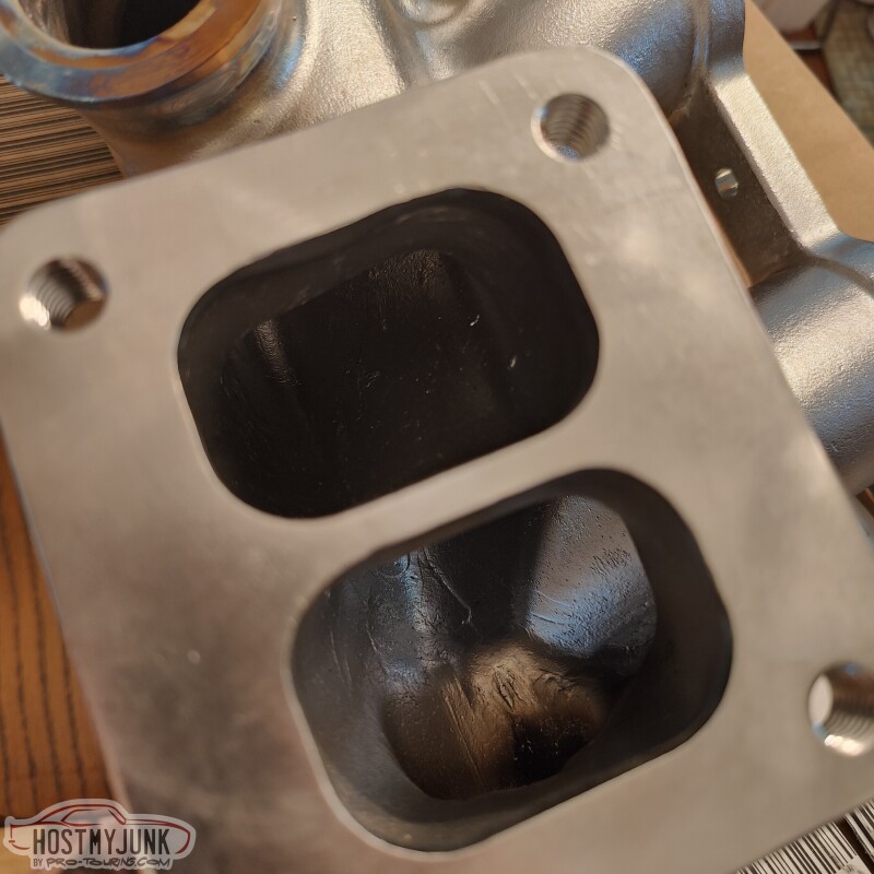
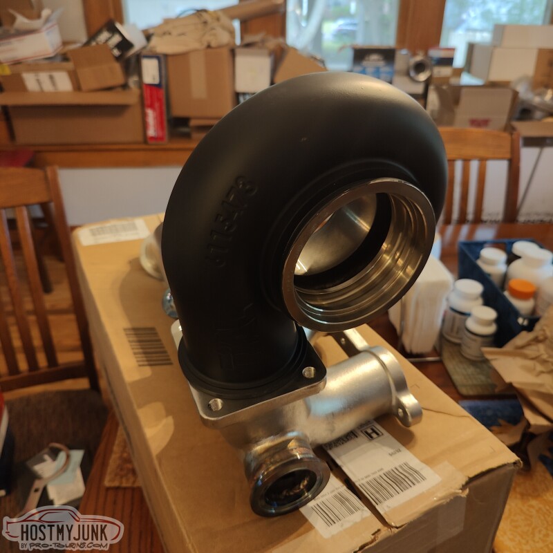
Just received the Summit manifold this morning. Some observations:
1. It is divided between the passenger and the driver's side banks, however, as noted before, this does not follow the LS firing order. I don't know what this means in practical terms.
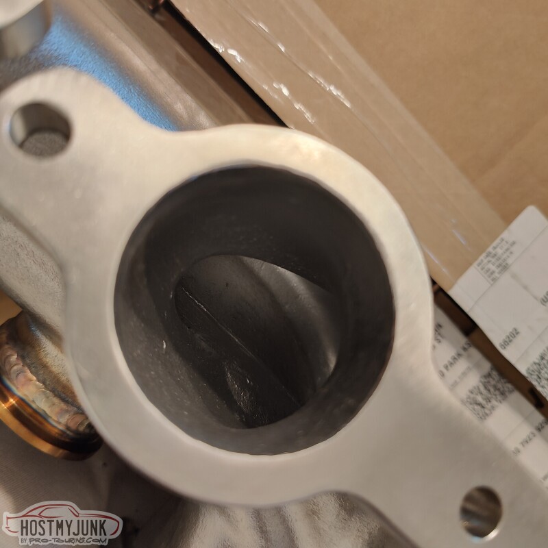
2. The casting, machine work, and welding are excellent.
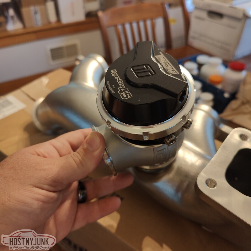
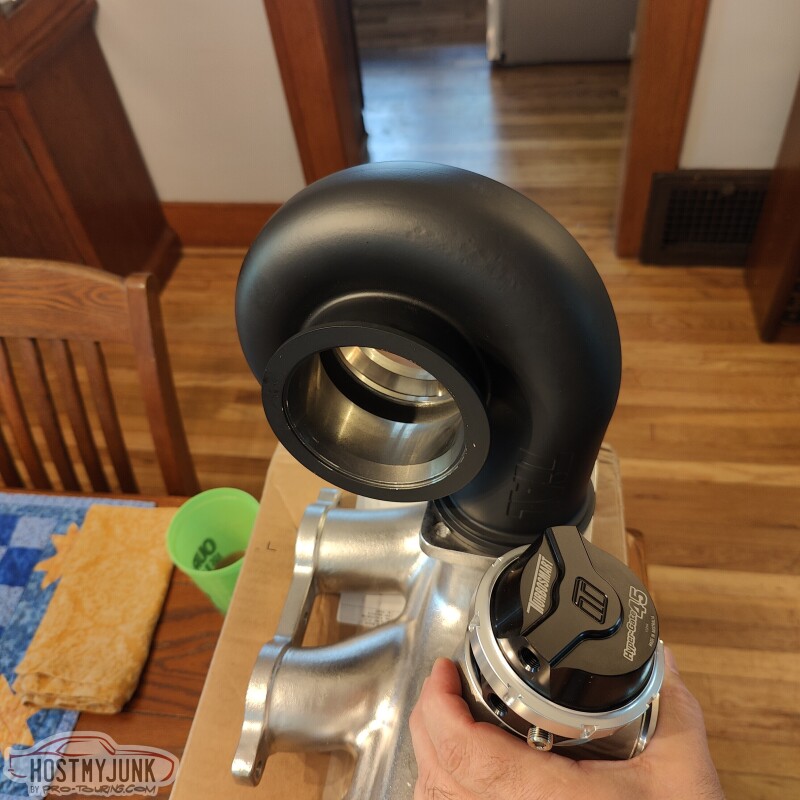
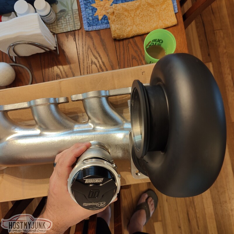
3. The welded WG flanges fit my TurboSmart 45mm wastegate perfectly.
4. A 4 inch downpipes looks to be a very tight fit against the waste gate. The TurboSmart waste gates are water cooled and I think this would be a smart feature to use in this installation.
5. It would be nice if the inlet side v-band and mating flange was included with the manifold.
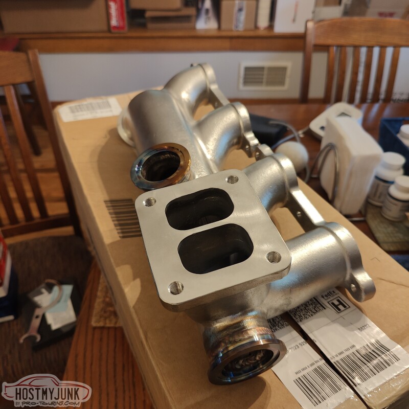
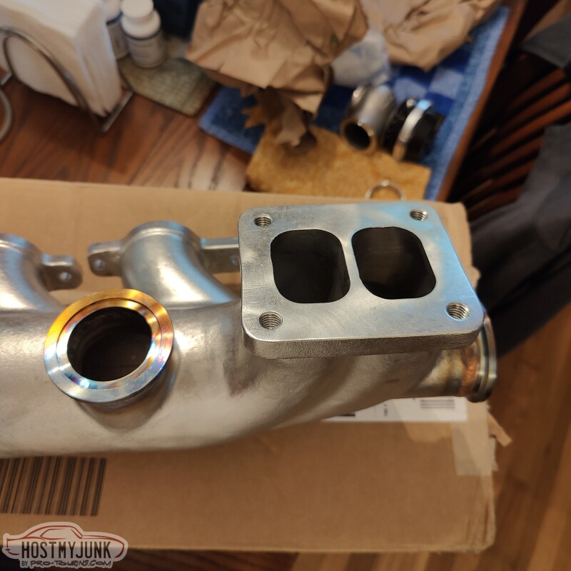
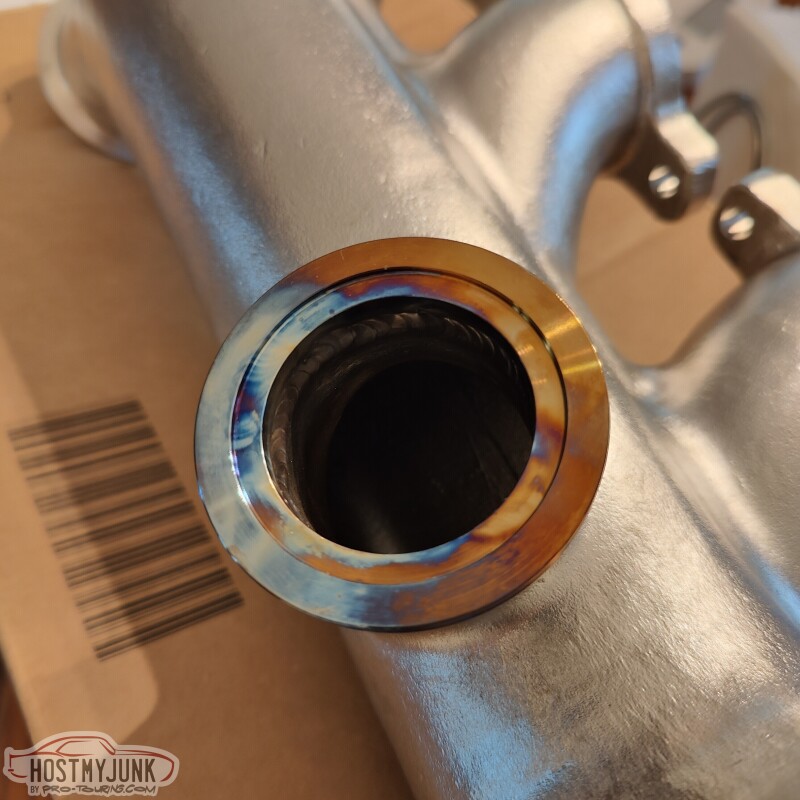
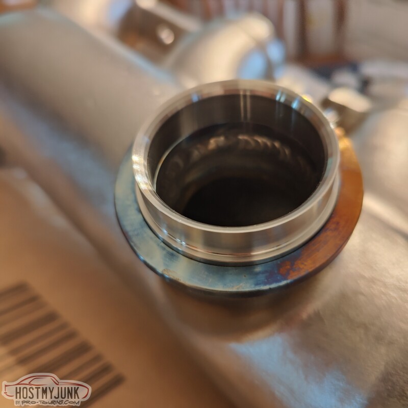
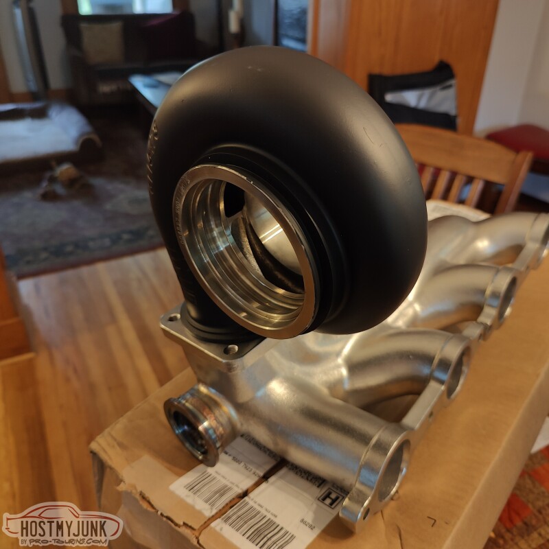
I will mock this up on the engine and post more pictures.
Andrew
Just received the Summit manifold this morning. Some observations:
1. It is divided between the passenger and the driver's side banks, however, as noted before, this does not follow the LS firing order. I don't know what this means in practical terms.
2. The casting, machine work, and welding are excellent.
3. The welded WG flanges fit my TurboSmart 45mm wastegate perfectly.
4. A 4 inch downpipes looks to be a very tight fit against the waste gate. The TurboSmart waste gates are water cooled and I think this would be a smart feature to use in this installation.
5. It would be nice if the inlet side v-band and mating flange was included with the manifold.
I will mock this up on the engine and post more pictures.
Andrew
07-26-2022 | 03:38 PM
#164
Thread Starter
Joined: Mar 2003
Posts: 10,244
Likes: 1,531
From: The City of Fountains
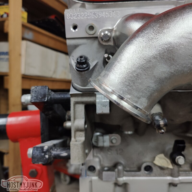
More pictures...
Observations:
1. The inlet flange is definitely not in the same location as the Holley manifold. If you look carefully and imagine where the firewall might be, the Summit manifold has a lot less space for a downpipe. This can probably be addressed by cutting off the inlet flange and positioning it in a similar location to the Holley manifold.
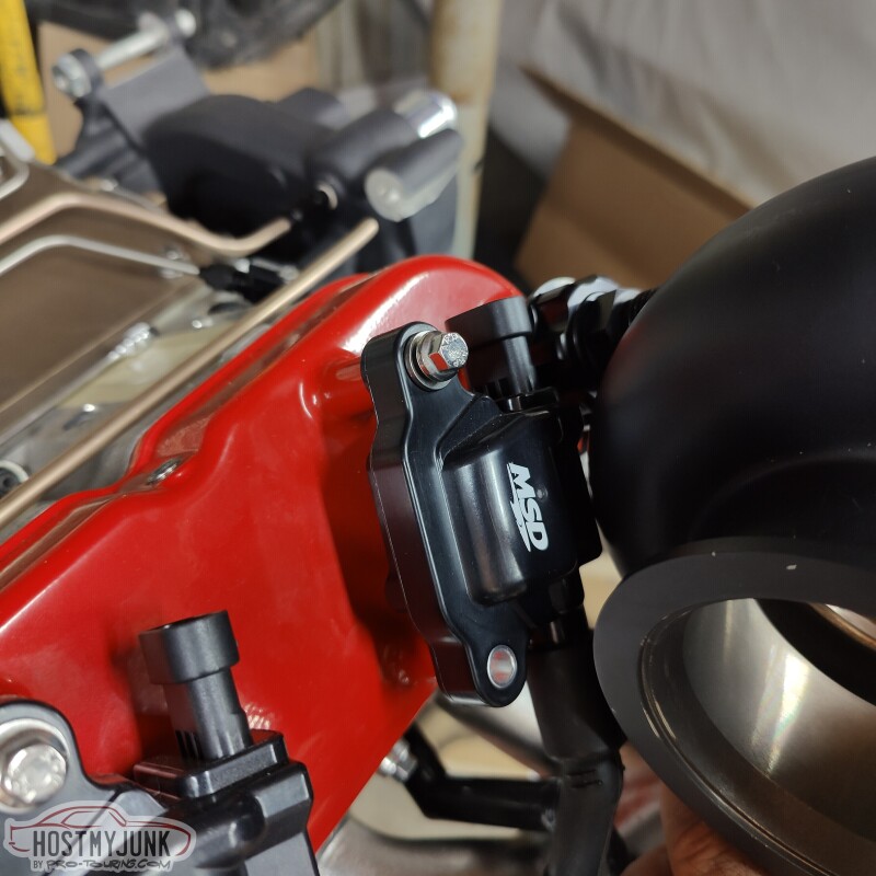
2. Tall valve covers are a no-go. In fact, even stock valve covers might cause the #2 coil to be cooked.
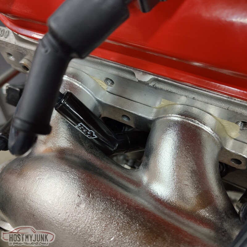
3. Accel ceramic 45 degree plug wires are a tight fit, and #6 cylinder doesn't fit at all.
These are just observations and by no means a judgement. Your mileage may vary...
Andrew
Observations:
1. The inlet flange is definitely not in the same location as the Holley manifold. If you look carefully and imagine where the firewall might be, the Summit manifold has a lot less space for a downpipe. This can probably be addressed by cutting off the inlet flange and positioning it in a similar location to the Holley manifold.
2. Tall valve covers are a no-go. In fact, even stock valve covers might cause the #2 coil to be cooked.
3. Accel ceramic 45 degree plug wires are a tight fit, and #6 cylinder doesn't fit at all.
These are just observations and by no means a judgement. Your mileage may vary...
Andrew
The following users liked this post:
n2xlr8n66 (07-29-2022)
07-26-2022 | 04:17 PM
#165
I kind of thought the coils could be a problem. Does it seem to be farther away from the engine than the Holley manifold, some bodies have interference with the upper control arm.
Thanks for sharing the pics.
Thanks for sharing the pics.
07-26-2022 | 06:06 PM
#166
Thread Starter
Joined: Mar 2003
Posts: 10,244
Likes: 1,531
From: The City of Fountains
Andrew
07-27-2022 | 05:36 AM
#167
Since I am mocking up stuff now I told him if he wanted to send me one I would test fit it, have a T4 80mm.
Be interesting since I am using stock VC's, coils. My 4" down pipe is easy since no AC box, gives some access to #8 spark plug, lol. I wasn't wild about the Holley manifold, but since I made a "stand" for the turbo I feel better about not just the pipe holding the turbo.
Be interesting since I am using stock VC's, coils. My 4" down pipe is easy since no AC box, gives some access to #8 spark plug, lol. I wasn't wild about the Holley manifold, but since I made a "stand" for the turbo I feel better about not just the pipe holding the turbo.
The following users liked this post:
Project GatTagO (07-27-2022)
07-27-2022 | 07:53 AM
#168
Thread Starter
Joined: Mar 2003
Posts: 10,244
Likes: 1,531
From: The City of Fountains
Since I am mocking up stuff now I told him if he wanted to send me one I would test fit it, have a T4 80mm.
Be interesting since I am using stock VC's, coils. My 4" down pipe is easy since no AC box, gives some access to #8 spark plug, lol. I wasn't wild about the Holley manifold, but since I made a "stand" for the turbo I feel better about not just the pipe holding the turbo.
Be interesting since I am using stock VC's, coils. My 4" down pipe is easy since no AC box, gives some access to #8 spark plug, lol. I wasn't wild about the Holley manifold, but since I made a "stand" for the turbo I feel better about not just the pipe holding the turbo.
What vehicle are you doing this installation on?
Andrew
07-27-2022 | 11:06 AM
#169


80 Malibu-it was just a simple bracket I put together, kind of held the turbo where I liked it, then made it. The T4 mount plate is round on the back side, so a 3" pipe fits w/o having to beat a pipe into a square hole, lol. Its nice because you only need the turbine on to make the down pipe, and I can make the 3" from the manifold w/o any of the turbo. Surprisingly the bracket holds the turbo really well, the 3" pipe will add to it. I dont have any of the old heater/AC stuff, so plenty of room to make #8 sparkplug not be a 3 hour deal, lol.
The following 2 users liked this post by forcd ind:
JinglingBaby (07-28-2022), n2xlr8n66 (07-29-2022)
07-29-2022 | 06:04 AM
#171
Yep, 4", I'll run it to the back bumper-since this car started out as a shell, no AC/heat box, using the block off plate allows a lot of room (prob Vintage air later on). I always try and give #8 plug as much room as possible, as it can be a bear-I have a couple welded up wrenches, lol. I think you still have the AC box, could be a tight fit.
07-29-2022 | 10:10 AM
#172
Thread Starter
Joined: Mar 2003
Posts: 10,244
Likes: 1,531
From: The City of Fountains
Yep, 4", I'll run it to the back bumper-since this car started out as a shell, no AC/heat box, using the block off plate allows a lot of room (prob Vintage air later on). I always try and give #8 plug as much room as possible, as it can be a bear-I have a couple welded up wrenches, lol. I think you still have the AC box, could be a tight fit.
Andrew
11-20-2022 | 09:21 PM
#173
Thread Starter
Joined: Mar 2003
Posts: 10,244
Likes: 1,531
From: The City of Fountains
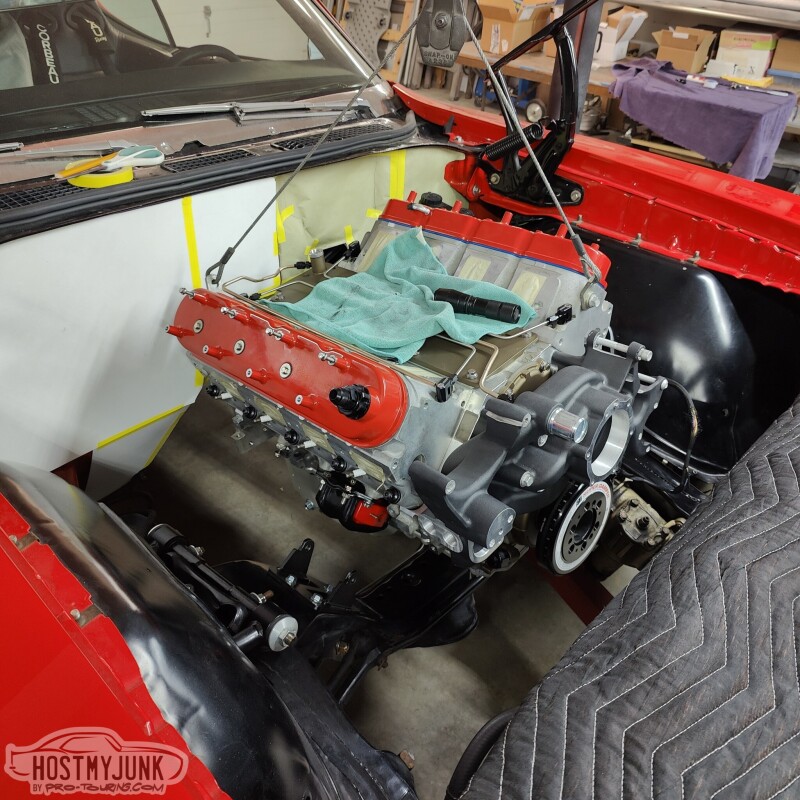
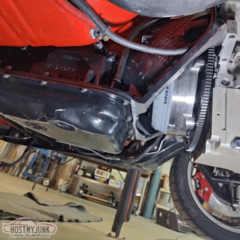
Today was a big day. I went over to Vic's house with the goal of mocking up the engine in the engine bay. I had confidence that the Holley swap components would not be an issues, but the big area of concern was the oil drain back fitting for the turbo on the side of the Holley 302-3 pan. Holley designed those drain backs in a Fox body Mustang, and when used with a GM A-body there was some concern that the fitting would hit the front crossmember.
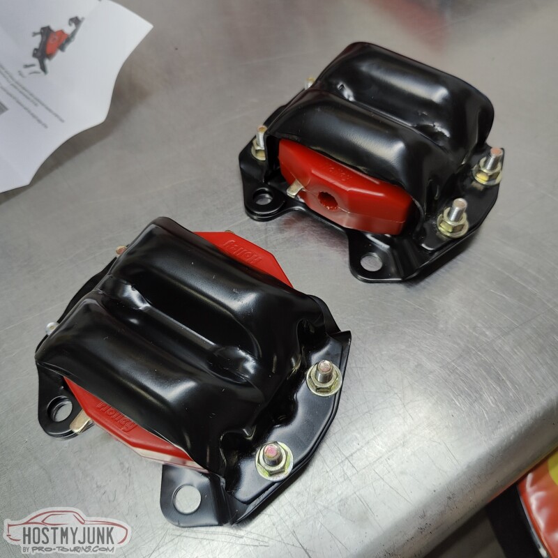
These are the Holley clamshells with the poly inserts. They are dimensionally identical to 4th gen Camaro engine mounts, except with a bolt together design and poly inserts.
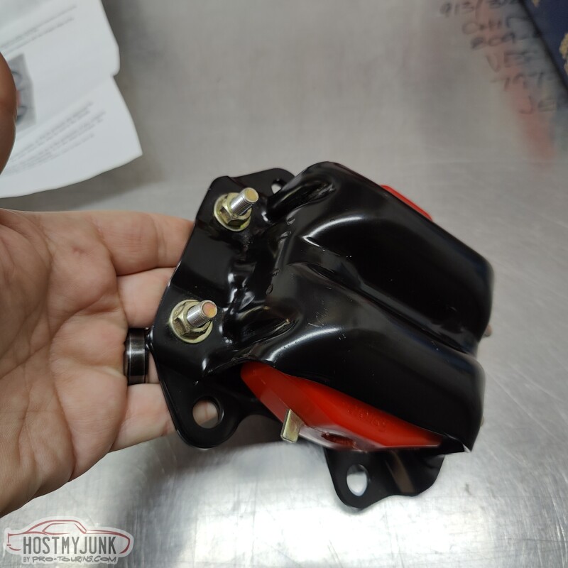
I am not sure why Holley includes such long bolts, but I decided to keep them and the included lock nuts. They will not be visible at all once everything is bolted to the engine.
After mocking up the engine the first time, it was clear that the oil drain fitting that I got was not going to work. At least not without some modifications.
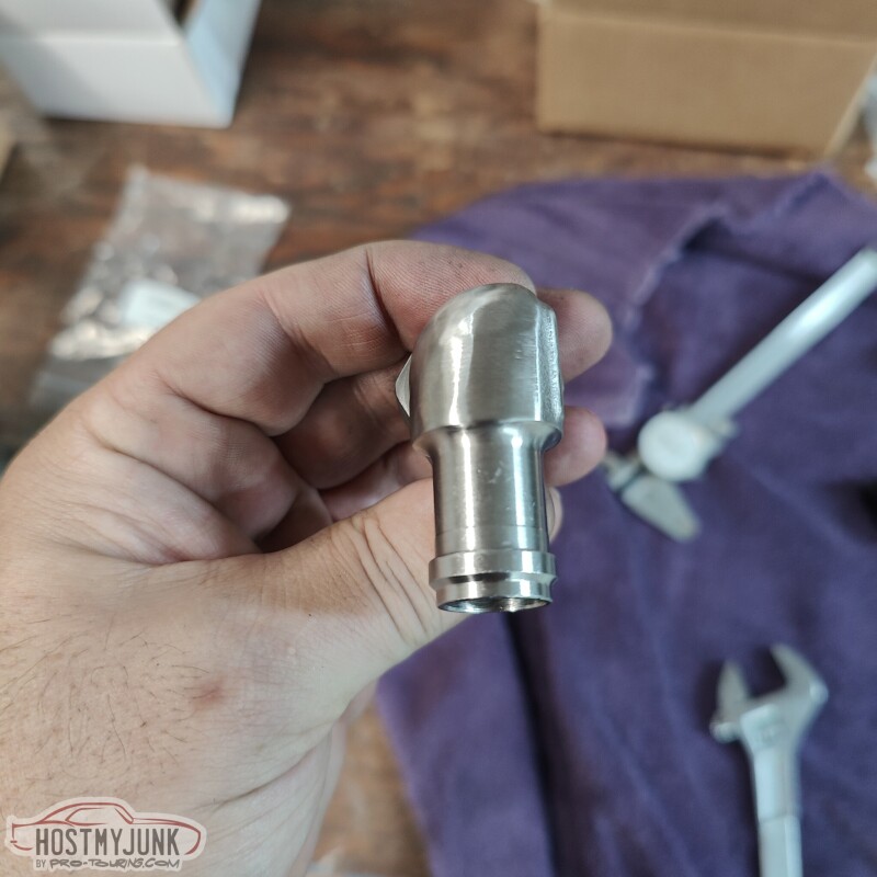
I can't believe I have gone this long without having a lathe and a mill. Both were used to modify the Earl's fitting in order to make it fit.
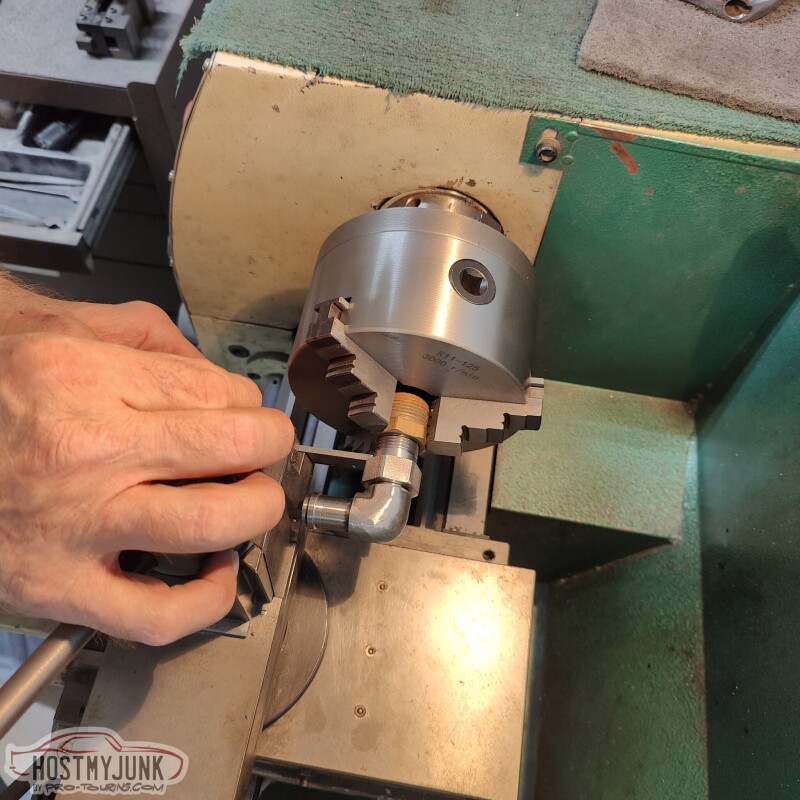
The lathe was used to back-cut the area between the end of the threads and the hex area. This was done so that the fitting can be installed deeper into the boss on the side of the pan. The mill was used to trim the end of the threads, because with the fitting screwed in deeper, it would hit the oil pick-up tube.
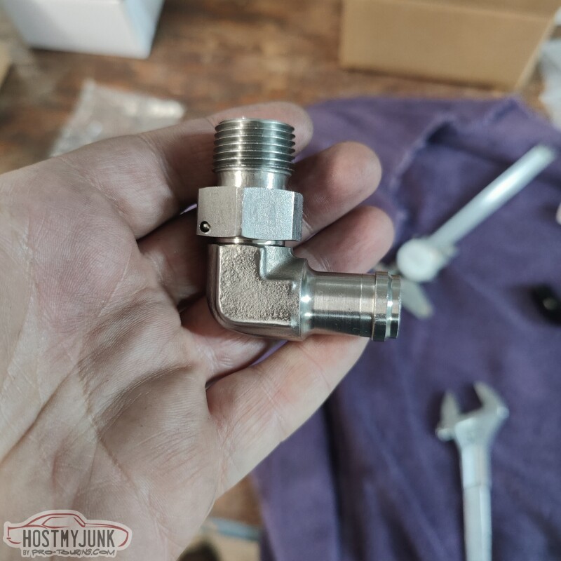
The outside of the fitting was also smoothed and contoured on the belt sander. It is a rather bulky fitting and there was plenty of material to remove in order for the fitting to match the contour of the front cross member. The pan was also removed in order to tap the 1/2" NPT threads a little deeper.
It took a total of six rounds to get it to the point where the engine mounts dropped into the frame stands and the mounting bolts to slide in.
The fitting has about 1/8" clearance against the crossmember, and it is able to pivot freely.
With some luck, the transmission and the converter will go in on Wednesday and then Vic can start the fabrication for the turbo hotside.
Andrew
These are the Holley clamshells with the poly inserts. They are dimensionally identical to 4th gen Camaro engine mounts, except with a bolt together design and poly inserts.
I am not sure why Holley includes such long bolts, but I decided to keep them and the included lock nuts. They will not be visible at all once everything is bolted to the engine.
After mocking up the engine the first time, it was clear that the oil drain fitting that I got was not going to work. At least not without some modifications.
I can't believe I have gone this long without having a lathe and a mill. Both were used to modify the Earl's fitting in order to make it fit.
The lathe was used to back-cut the area between the end of the threads and the hex area. This was done so that the fitting can be installed deeper into the boss on the side of the pan. The mill was used to trim the end of the threads, because with the fitting screwed in deeper, it would hit the oil pick-up tube.
The outside of the fitting was also smoothed and contoured on the belt sander. It is a rather bulky fitting and there was plenty of material to remove in order for the fitting to match the contour of the front cross member. The pan was also removed in order to tap the 1/2" NPT threads a little deeper.
It took a total of six rounds to get it to the point where the engine mounts dropped into the frame stands and the mounting bolts to slide in.
The fitting has about 1/8" clearance against the crossmember, and it is able to pivot freely.
With some luck, the transmission and the converter will go in on Wednesday and then Vic can start the fabrication for the turbo hotside.
Andrew
11-21-2022 | 08:41 AM
#174
Looking good, I had to do the same with a fuel rail fitting, was hitting the alt, so my buddy trimmed the hex nut. Are those Holley LS/A body mounts, they are diff than the setup for G bodies, where the clamshell mounts to the frame. Hopeful they give better clearance with the Holley manifold, as mine are to close for comfort, hope the dont melt, lol. I am at the running, driving stage, just around the block, I used that Zy Coat coating, def not a replacement for wrap.
11-21-2022 | 09:19 AM
#175
Thread Starter
Joined: Mar 2003
Posts: 10,244
Likes: 1,531
From: The City of Fountains
Looking good, I had to do the same with a fuel rail fitting, was hitting the alt, so my buddy trimmed the hex nut. Are those Holley LS/A body mounts, they are diff than the setup for G bodies, where the clamshell mounts to the frame. Hopeful they give better clearance with the Holley manifold, as mine are to close for comfort, hope the dont melt, lol. I am at the running, driving stage, just around the block, I used that Zy Coat coating, def not a replacement for wrap.
Yes, all Holley swap components. Depending on the chassis, they use different combinations of engine and frame mounts.
Hopefully the Cerakote holds up well on the exhaust.
Andrew
11-23-2022 | 09:08 PM
#176
Thread Starter
Joined: Mar 2003
Posts: 10,244
Likes: 1,531
From: The City of Fountains
Today was another big day. I hauled all of the parts that were needed to install the transmission to Vic's house. We started around 10am and made excellent progress.
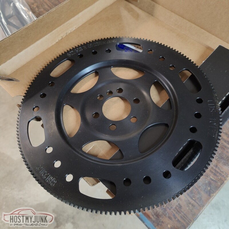
This is a billet steel SFI approved flex plate from Circle D. It looks amazing and has 6 converter bolts to match the Circle D billet triple disk converter.
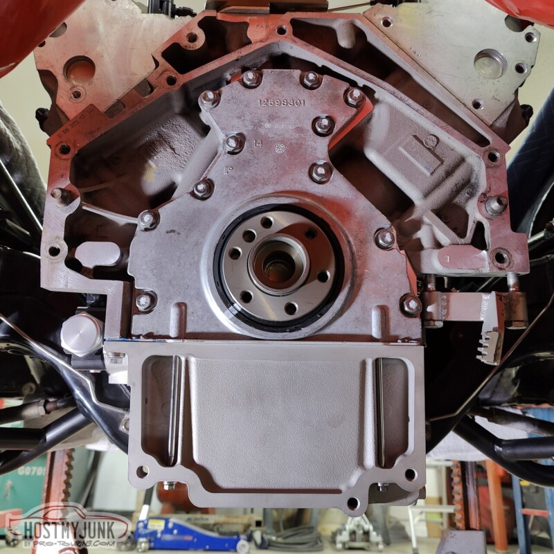
It is nice working with a clean block and a new crank. Just to make sure everything was good, I hand threaded the ARP flex plate bolts into the crank before doing anything else.
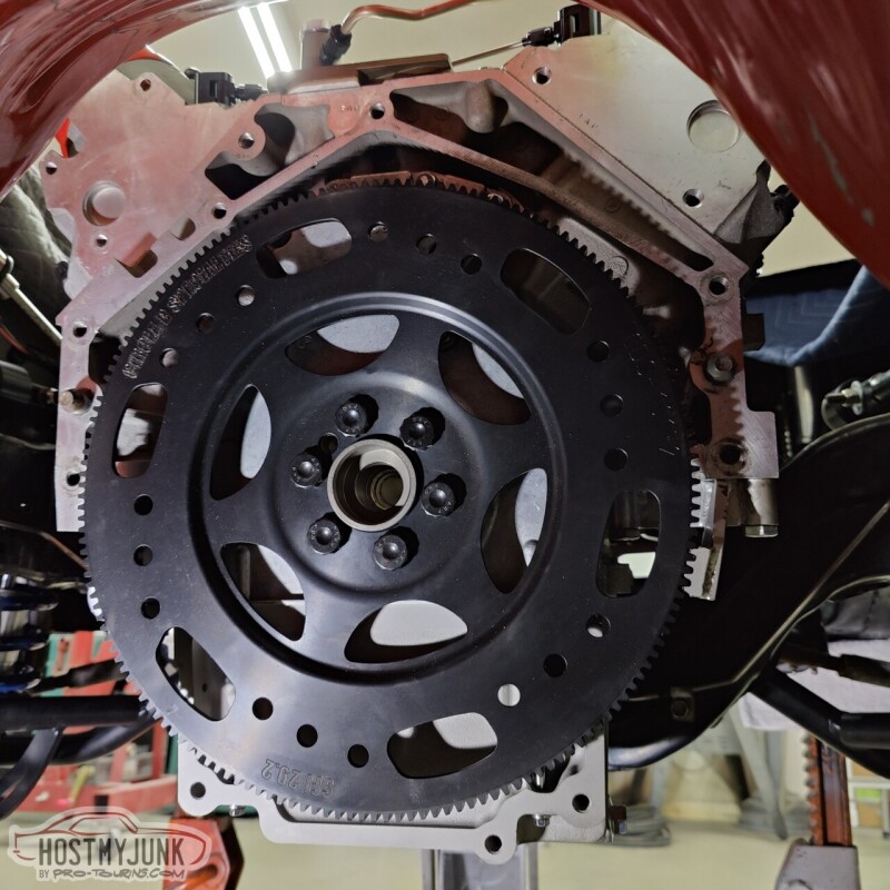
The flex plate went on without any drama and was torqued to 75lb/ft using blue Loctite. The flex plate locking tool came in handy for this task to keep the crank from rotating.
After installing the converter into the transmission (not sure why I didn't get a picture), it was time to wrestle this beast of a transmission under the car. We had some jack stands under the rear axle and jack stands under the front frame horns to get the car high enough.
It was easy enough to get a jack under the tailshaft housing, but getting the front of the transmission up was the big challenge. I suggested using the engine hoist and attaching a strap to two bolts in the transmission case. This worked great! We got the transmission high enough to slip a transmission jack under the pan for extra safety, then slowly working it up until the transmission slipped on to the dowel pins.
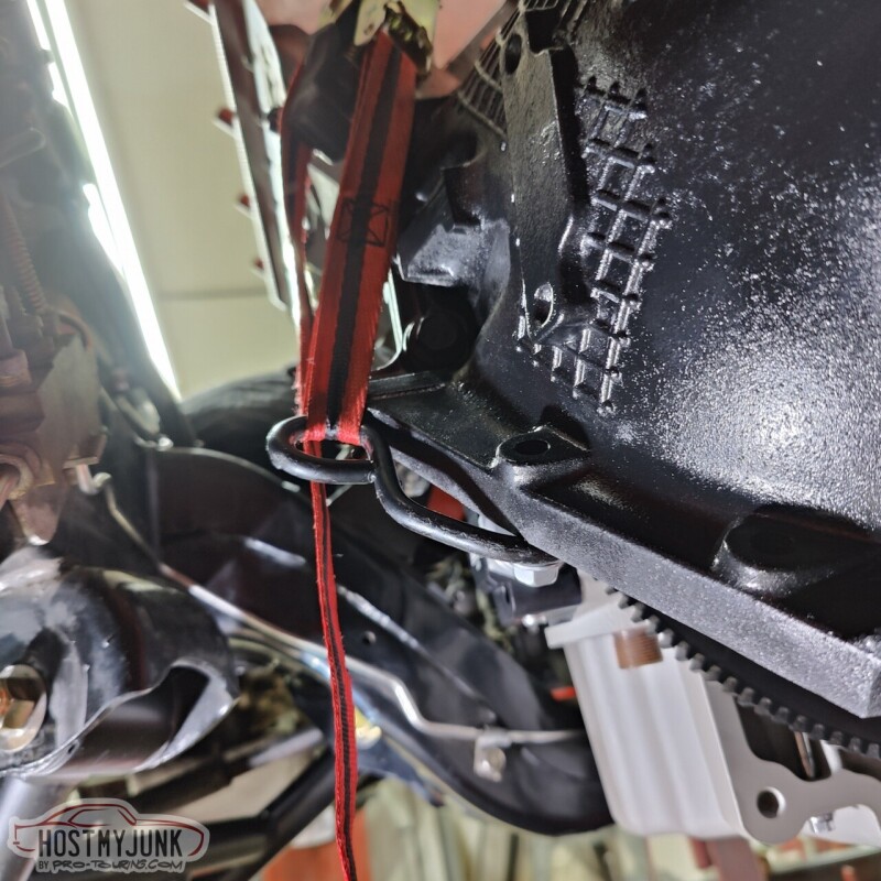
There was about a .130" gap between the converter and the flex plate, which is perfect. You can see that the pan is basically level with the frame.
We followed the instructions that came with the Holley transmission crossmember, but had a little trouble with the transmission mount that I got. I got an Energy Suspension poly mount, which is not what is specified in the instructions (should have read them before buying it). After a little searching around on Rockauto, we got a part number for a 70 GTO TH400 mount, Anchor PN 2378. The local parts store had one in stock and it ended up being about 1/2" shorter than the Energy Suspension mount. This allowed the crossmember to slip under the transmission easily, with about 3/8" of clearance.
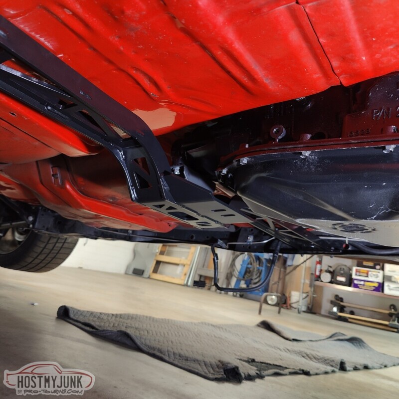
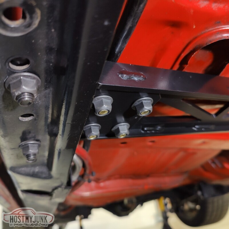
The left side of the crossmember slips over the frame rail, while the right side (shown here) has a separate pad that slips over the frame rail and the crossmember sits on top. This makes for a really solid installation.
Part of the reason I ever started this project was to redo the engine and transmission mounts and use a better fitting oil pan. I can't say enough about how well the Holley swap components are engineered to work together and how well everything fit together. In this day and age, it is hard to find parts that don't need some sort of modification to work as intended. We didn't have to modify anything!
Now that the engine and transmission are in their place, the fun stuff can start...
Andrew
This is a billet steel SFI approved flex plate from Circle D. It looks amazing and has 6 converter bolts to match the Circle D billet triple disk converter.
It is nice working with a clean block and a new crank. Just to make sure everything was good, I hand threaded the ARP flex plate bolts into the crank before doing anything else.
The flex plate went on without any drama and was torqued to 75lb/ft using blue Loctite. The flex plate locking tool came in handy for this task to keep the crank from rotating.
After installing the converter into the transmission (not sure why I didn't get a picture), it was time to wrestle this beast of a transmission under the car. We had some jack stands under the rear axle and jack stands under the front frame horns to get the car high enough.
It was easy enough to get a jack under the tailshaft housing, but getting the front of the transmission up was the big challenge. I suggested using the engine hoist and attaching a strap to two bolts in the transmission case. This worked great! We got the transmission high enough to slip a transmission jack under the pan for extra safety, then slowly working it up until the transmission slipped on to the dowel pins.
There was about a .130" gap between the converter and the flex plate, which is perfect. You can see that the pan is basically level with the frame.
We followed the instructions that came with the Holley transmission crossmember, but had a little trouble with the transmission mount that I got. I got an Energy Suspension poly mount, which is not what is specified in the instructions (should have read them before buying it). After a little searching around on Rockauto, we got a part number for a 70 GTO TH400 mount, Anchor PN 2378. The local parts store had one in stock and it ended up being about 1/2" shorter than the Energy Suspension mount. This allowed the crossmember to slip under the transmission easily, with about 3/8" of clearance.
The left side of the crossmember slips over the frame rail, while the right side (shown here) has a separate pad that slips over the frame rail and the crossmember sits on top. This makes for a really solid installation.
Part of the reason I ever started this project was to redo the engine and transmission mounts and use a better fitting oil pan. I can't say enough about how well the Holley swap components are engineered to work together and how well everything fit together. In this day and age, it is hard to find parts that don't need some sort of modification to work as intended. We didn't have to modify anything!
Now that the engine and transmission are in their place, the fun stuff can start...
Andrew
The following 4 users liked this post by Project GatTagO:
11-25-2022 | 10:38 PM
#177
Thread Starter
Joined: Mar 2003
Posts: 10,244
Likes: 1,531
From: The City of Fountains
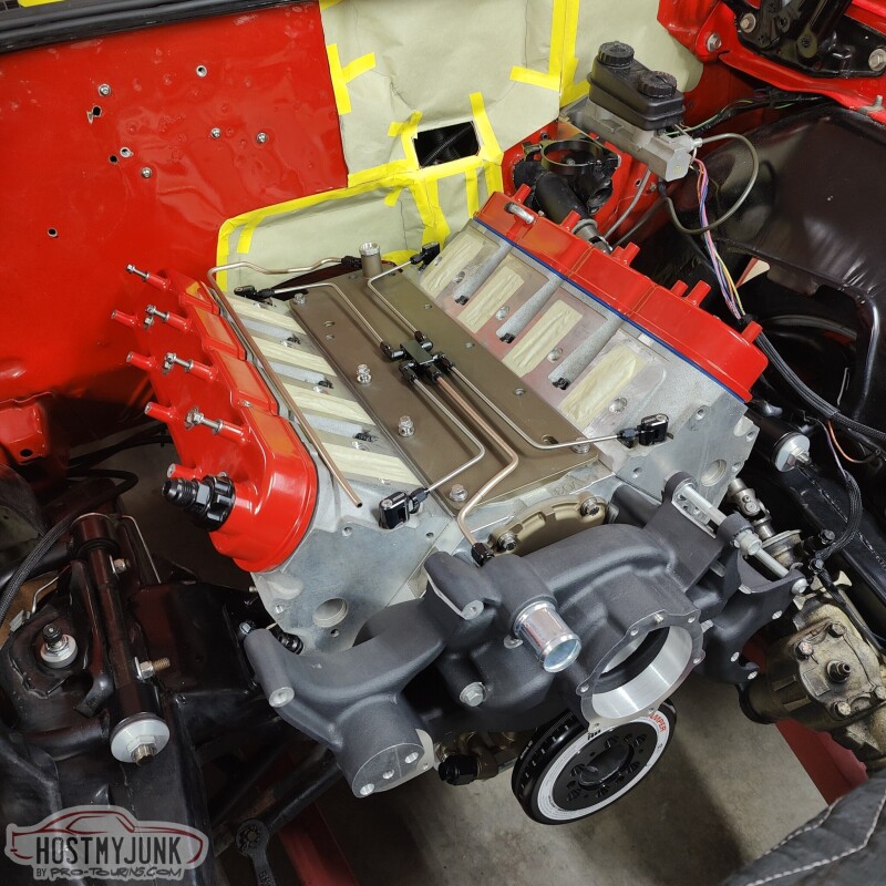
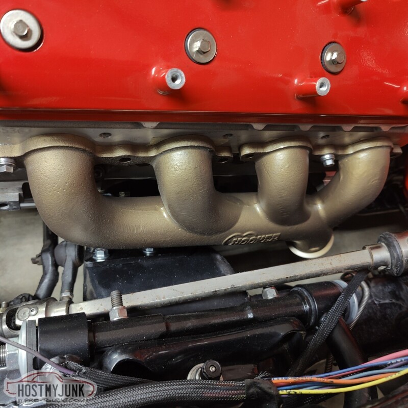
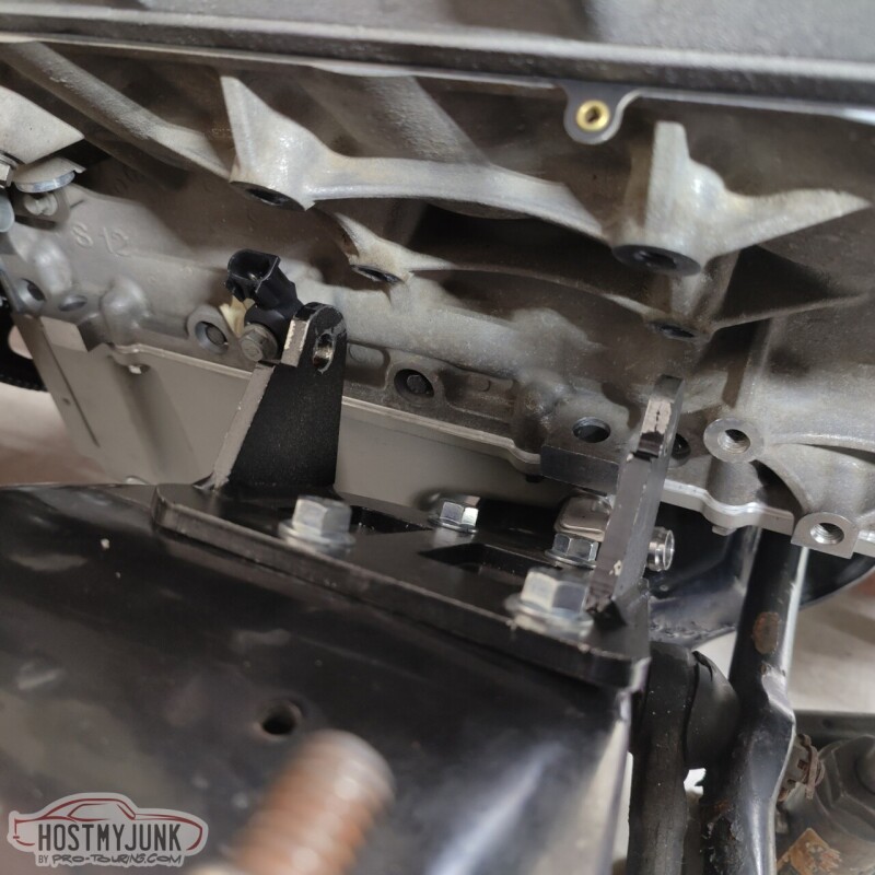
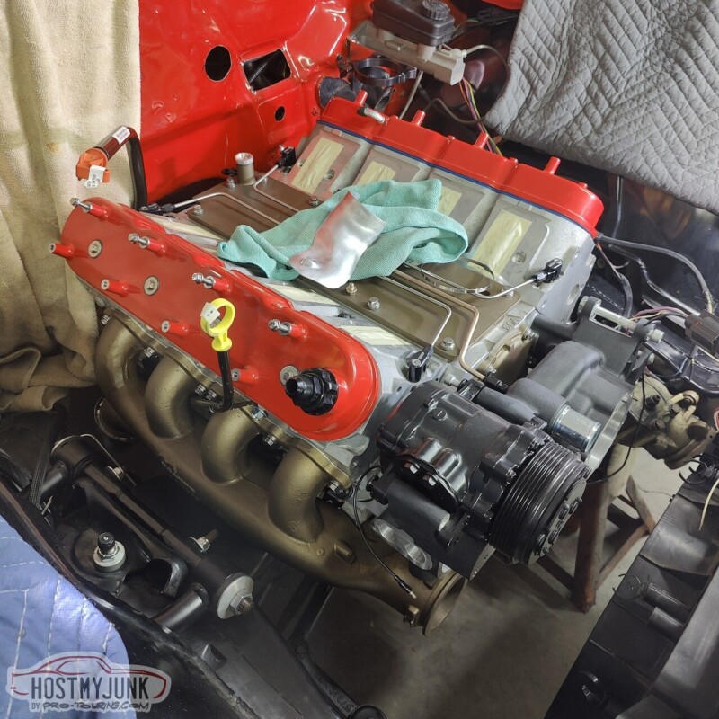
Today started out well. The driver's side manifold installed with zero issues and fits perfectly.
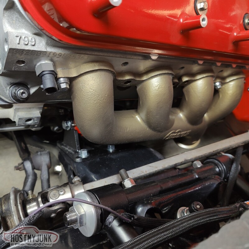
The same could not be said for the passenger side. I can't believe that I never mocked up that side with the engine mounts when the engine was on the stand...
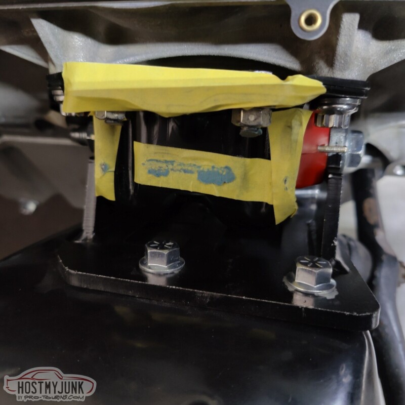
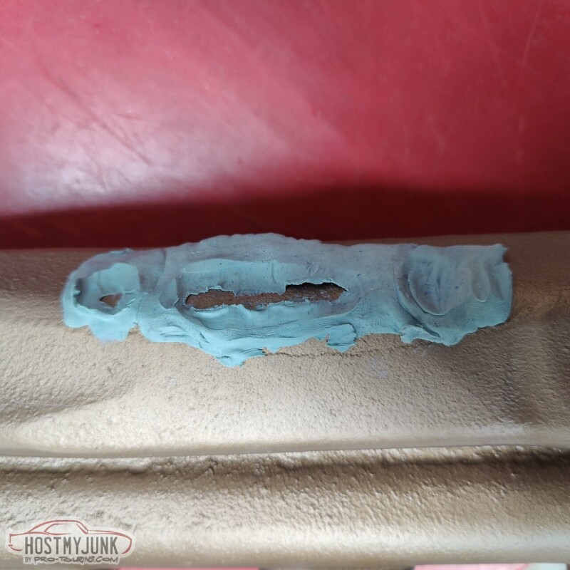
When I went to install it on the engine, it was obvious that that manifold was hitting something and it was not sitting flush with the head. We used some clay on the manifold and here you can see where it was making contact with the engine mount.
We were pretty confident that the engine mount clam shells were assembled correctly and the poly inserts were oriented properly. Otherwise the engine wouldn't have fit into the frame stands as well as it did.
Here you can see the contact spot on the manifold.
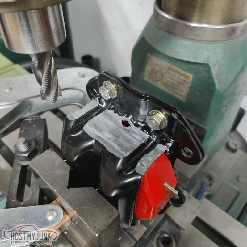
We jacked up the front right corner of the engine and removed the engine mount.
I really didn't care why it was happening, we had to fix it and keep moving forward. Vic chucked up the engine mount in the mill and we took off about .080". The material is pretty thick, so we felt confident that the integrity of the mount was not compromised. Besides, the upper clam shell is really not stressed when it is installed on the passenger side.
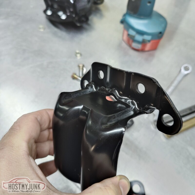
Here is the final version of the passenger side mount after a quick coat of paint. Onward!
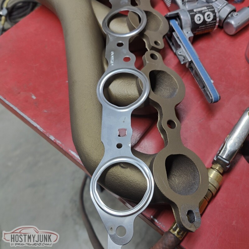
We used Mahle MLS exhaust manifold gaskets. These should seal really well and hold up to the heat.
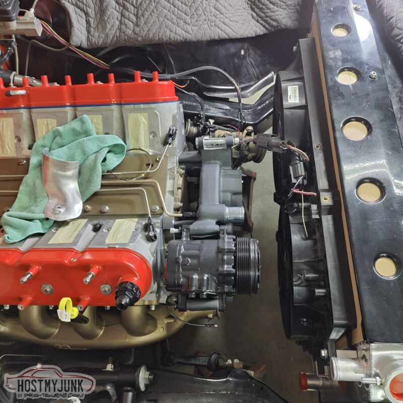
We then installed the radiator and fans to see what kind of room we had to work with.
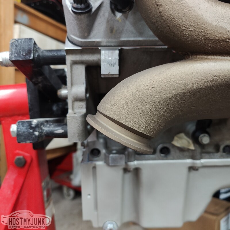
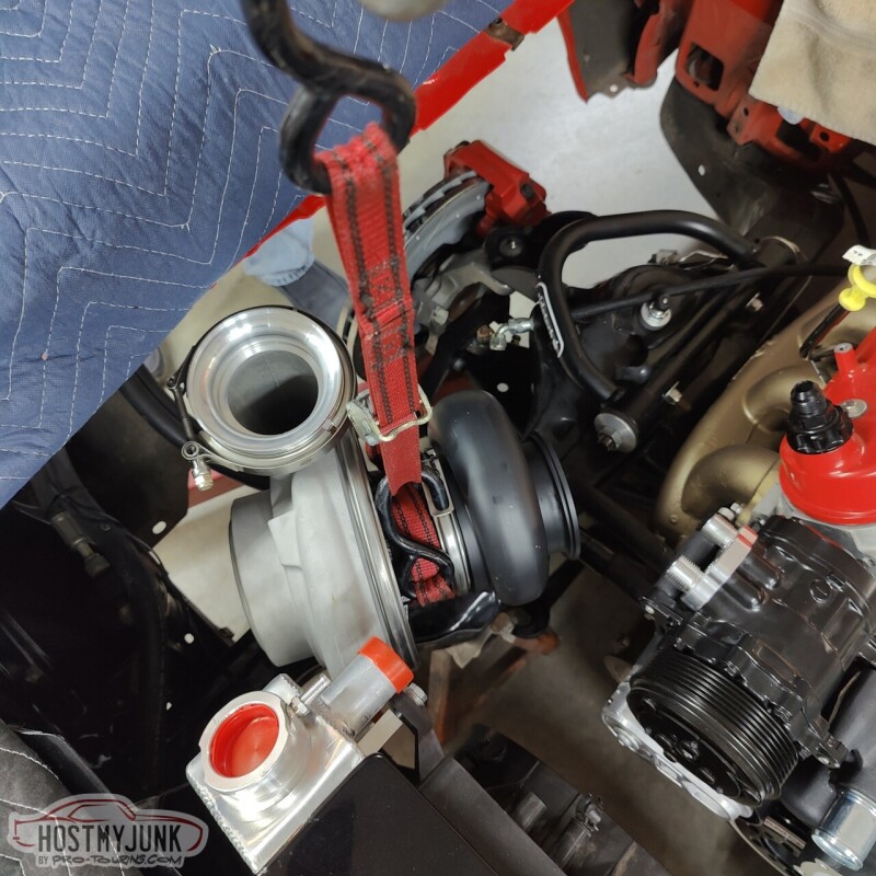
Here is the 135 degree elbow that I got from Stainless Bros as the starting point for the turbine up-pipe.

We're thinking the turbo is going to end up next to the AC compressor, oriented parallel to the engine.
Sunday we are going to do some more mocking up and maybe make a temporary mount for the turbo so that the pipes can be figured out.
Andrew
The same could not be said for the passenger side. I can't believe that I never mocked up that side with the engine mounts when the engine was on the stand...
When I went to install it on the engine, it was obvious that that manifold was hitting something and it was not sitting flush with the head. We used some clay on the manifold and here you can see where it was making contact with the engine mount.
We were pretty confident that the engine mount clam shells were assembled correctly and the poly inserts were oriented properly. Otherwise the engine wouldn't have fit into the frame stands as well as it did.
Here you can see the contact spot on the manifold.
We jacked up the front right corner of the engine and removed the engine mount.
I really didn't care why it was happening, we had to fix it and keep moving forward. Vic chucked up the engine mount in the mill and we took off about .080". The material is pretty thick, so we felt confident that the integrity of the mount was not compromised. Besides, the upper clam shell is really not stressed when it is installed on the passenger side.
Here is the final version of the passenger side mount after a quick coat of paint. Onward!
We used Mahle MLS exhaust manifold gaskets. These should seal really well and hold up to the heat.
We then installed the radiator and fans to see what kind of room we had to work with.
Here is the 135 degree elbow that I got from Stainless Bros as the starting point for the turbine up-pipe.
We're thinking the turbo is going to end up next to the AC compressor, oriented parallel to the engine.
Sunday we are going to do some more mocking up and maybe make a temporary mount for the turbo so that the pipes can be figured out.
Andrew
11-26-2022 | 06:14 AM
#178
Well, we now know they never mocked up their turbo manifold on a G or A body using their mounting system, lol. You were lucky, easy fix. Mine, not so much. But, its hot rodding, we make stuff fit.
11-26-2022 | 09:02 AM
#179
Thread Starter
Joined: Mar 2003
Posts: 10,244
Likes: 1,531
From: The City of Fountains
I actually got a mount from AutoZone and just my looking at it, I don't think it would have made any difference, so I took it back.
In any case, progress is being made.
Andrew
11-27-2022 | 04:54 PM
#180
Thread Starter
Joined: Mar 2003
Posts: 10,244
Likes: 1,531
From: The City of Fountains
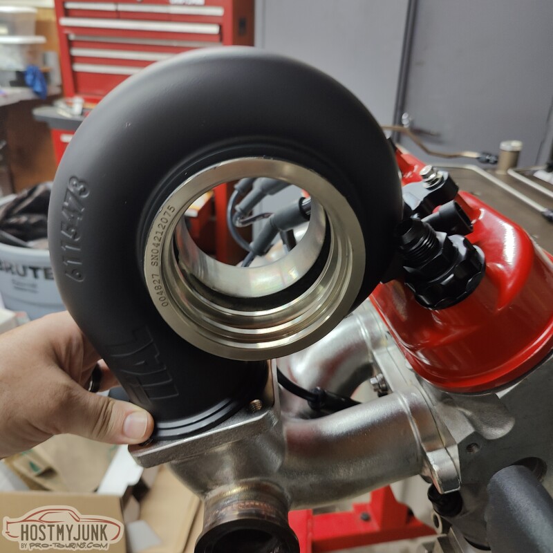
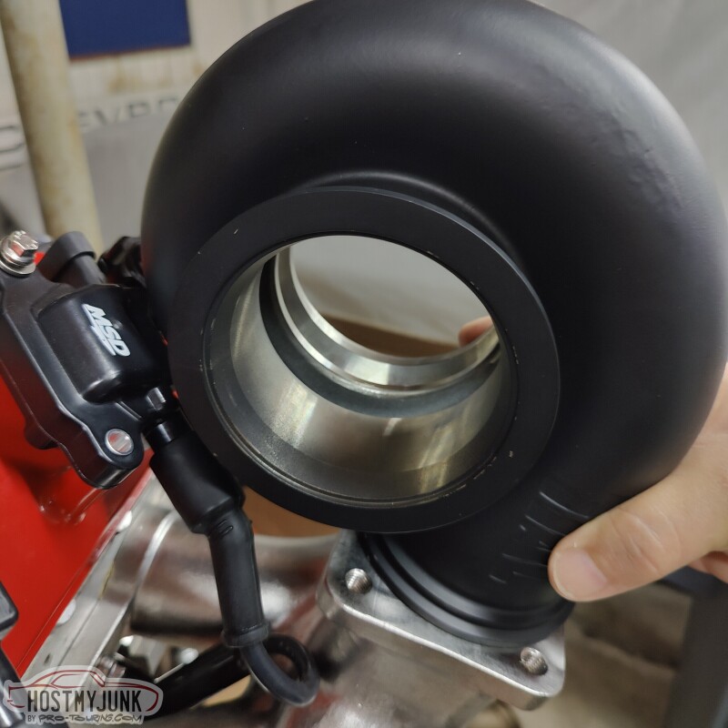
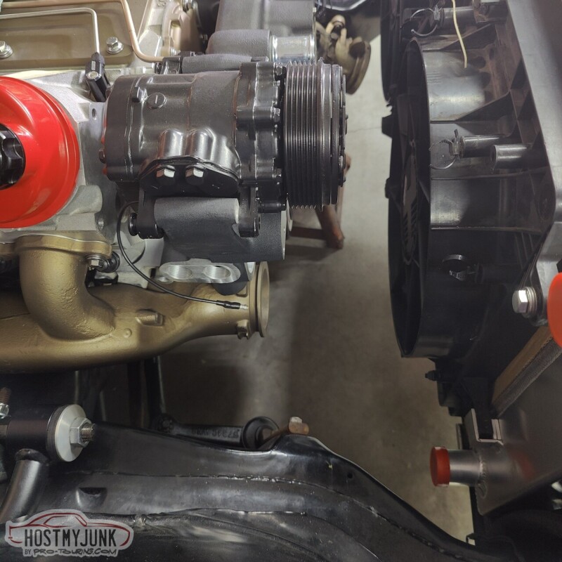
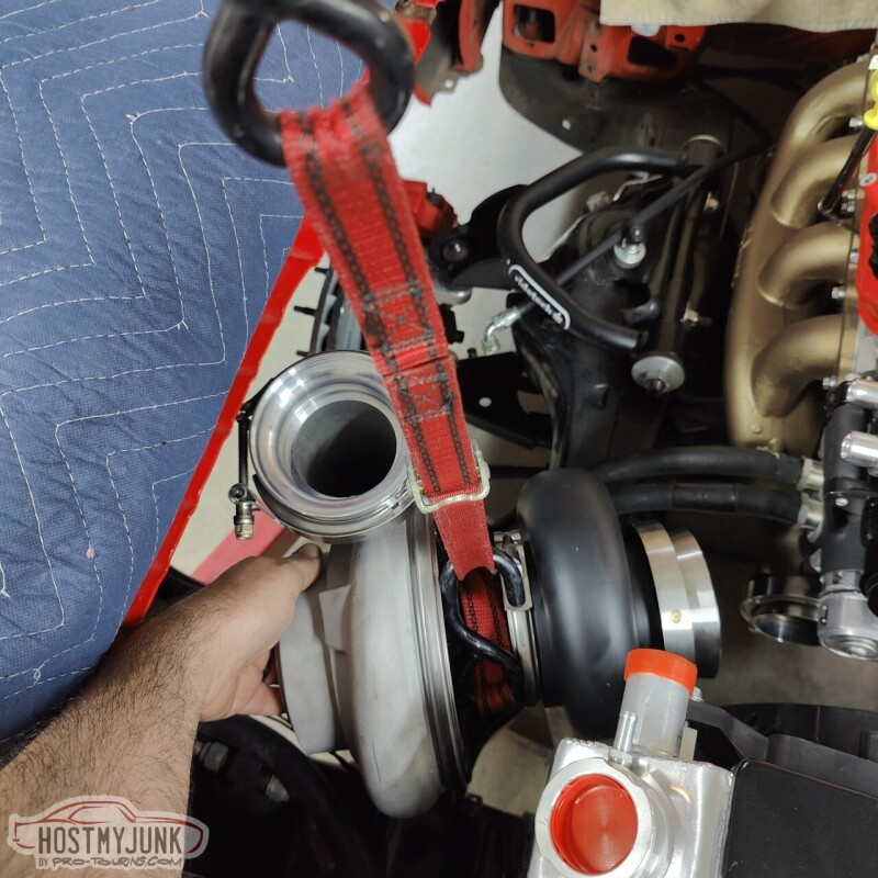
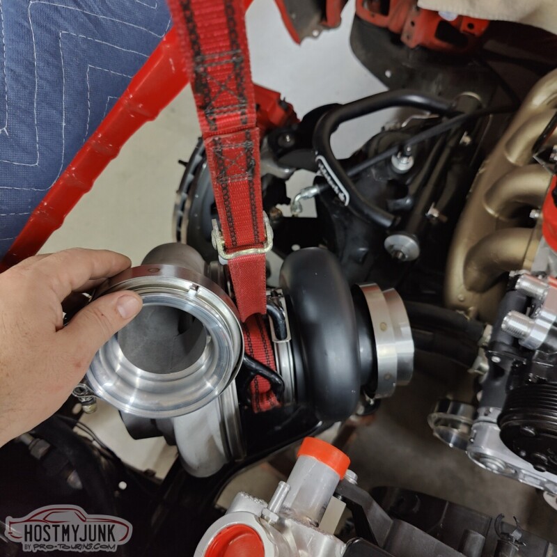
Today we attempted to mock up an approximate location for the turbo. We hung it on an engine hoist and moved it around. The following pictures show various options.
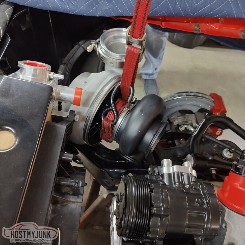
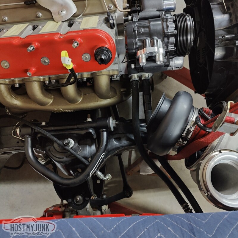
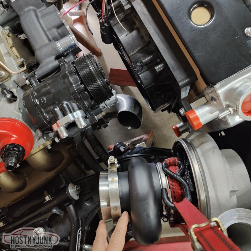
The challenge is to find a location that clears the following:
Heater hoses
AC lines
Lower radiator hose
Air filter
Bottom line, I don't think any position will work. This thing is just too big...
Andrew
The challenge is to find a location that clears the following:
Heater hoses
AC lines
Lower radiator hose
Air filter
Bottom line, I don't think any position will work. This thing is just too big...
Andrew