PVC Catch can system.... Final conclusive answer
 07-14-2007, 03:46 PM
#101
TECH Enthusiast
iTrader: (5)

Join Date: Dec 2005
Location: Strawberry Point, IA
Posts: 553
Likes: 0
Received 0 Likes
on
0 Posts
Originally Posted by JMBLOWNWS6
Yup  Ryan @ A bear. $750 for the covers. No part number. I had allready come up with this idea from my buddie Danny. So we did it on my his vette which I have allready posted.
Ryan @ A bear. $750 for the covers. No part number. I had allready come up with this idea from my buddie Danny. So we did it on my his vette which I have allready posted.Thanks - Ron


 07-14-2007, 09:17 PM
#103
TECH Fanatic
iTrader: (9)

Join Date: Apr 2005
Location: ATL/Savannah Georgia
Posts: 1,395
Likes: 0
Received 0 Likes
on
0 Posts
Originally Posted by nossty1
Why not use 1 husky for each cover? They are cheap enough and it would just flow better.
mondi2002 im confused by your setup. you have the back two ports y-ing into the PCV valve and then to a catch can? TB is plugged and where is the intake running to and front pass valve cover?
07-15-2007, 01:02 PM
#104
11 Second Club
iTrader: (11)
Join Date: Jul 2005
Location: CLARENCE, NY
Posts: 248
Likes: 0
Received 0 Likes
on
0 Posts

Originally Posted by JAvenger007
That could work and then just run a filter off of each (or just cap the one side).
mondi2002 im confused by your setup. you have the back two ports y-ing into the PCV valve and then to a catch can? TB is plugged and where is the intake running to and front pass valve cover?
mondi2002 im confused by your setup. you have the back two ports y-ing into the PCV valve and then to a catch can? TB is plugged and where is the intake running to and front pass valve cover?
You should not put vacuum on this, its like sucking on both ends of a straw.
Since I have a procharger, must cap off the TB port and vent the line to the ground. I am using the intake port to control my Bypass valve for the procharger. Seems that most use the brake booster line for that though. I am not sure why? I do have my boost gauge hooked up on the brake booster.
07-17-2007, 12:29 AM
#105
TECH Enthusiast
Join Date: Sep 2004
Location: Clarksville,Tn
Posts: 595
Likes: 0
Received 0 Likes
on
0 Posts
All I'm using is a small water seperator I bought at Lowes. Comes off the valve cover into the seperator then into the suction side of the blower. It actually pulls a vacuum on the crankcase. When I shut the car off I can hear air being sucked back in the motor around the grommet on the valve cover. I've got the same thing on the pcv valve but this is a custom intake and the baffle on the underside of the intake I made for the pcv isn't working too well. Sucks alot of oil in there. Thinking about just capping it off at the pcv valve and seeing how just pulling from the valve cover does. This is a roots blower by the way with only about 6-7 lbs. but the motor has 145,000 on it.
07-17-2007, 09:11 AM
#106
TECH Regular
Thread Starter
iTrader: (3)

Join Date: Jul 2005
Location: Bossier City LA
Posts: 449
Likes: 0
Received 0 Likes
on
0 Posts
As with so many threads like this one.... many opinions have surfaced, many options have surfaced. Can we come to a comprehensive, cost effective.... simple solution we can put on paper... possibly a sticky and put this to bed? Once again, I am not the sharpest knife in the drawer, however I can follow a diagram and read directions. Thanks for everyones input... lets see if we can consolidate all this info and put a diagram together so everyone can have an operational cost effective system.
07-17-2007, 12:15 PM
#107
TECH Resident
Join Date: Jan 2007
Location: Texas
Posts: 751
Likes: 0
Received 0 Likes
on
0 Posts
Originally Posted by koji777
As with so many threads like this one.... many opinions have surfaced, many options have surfaced. Can we come to a comprehensive, cost effective.... simple solution we can put on paper... possibly a sticky and put this to bed? Once again, I am not the sharpest knife in the drawer, however I can follow a diagram and read directions. Thanks for everyones input... lets see if we can consolidate all this info and put a diagram together so everyone can have an operational cost effective system.
I agree, after all we are dealing with the physical world of "forced induction". There should be some configuration that almost everybody agrees would be optimal as far as the systems ability to capture oil in a boosted environment
 07-20-2007, 10:12 PM
#109
TECH Apprentice
iTrader: (5)
Join Date: Oct 2003
Location: Glendale,AZ
Posts: 382
Likes: 0
Received 0 Likes
on
0 Posts
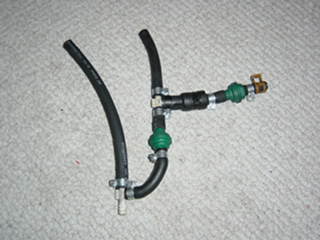
Here's My set up. I think its clean relitively simple, and keeps the PCV system stock while not under boost. It also vents all three ports to atmosphere through a catch can while under boost. Probably only good for 500-600 rwhp. The big boys just need to vent theirs to atmosphere all day long.
1. The port on the throttle body was pluged with a 1/8 brass pipe plug.
2. The 3/8 hose on the top left of the picture connects to the front pass side valve cover port.
3. The 3/8 hose on the top right connects to the factory line that connects both rear ports. I had to cut off about 4" off the factory hard plastic line.
4. The line to the far right connects to intake maniold vacuum.
5. The line at the bottom connects to a catch can.
6. The check valve on the right only allows the intake manifold to suck
7. The lower check valve allows the system to pull crankcase gasses through the stock PCV system, while under manifold vacuum and then vent all three ports to atmosphere under boost.
07-20-2007, 10:20 PM
#110
TECH Apprentice
iTrader: (8)

Join Date: Oct 2003
Location: Ingleside, Texas
Posts: 383
Likes: 0
Received 0 Likes
on
0 Posts
Ok... stupid question I just wanted to ask this.
Since I have the LS6 valley cover wouldn't it just be possible to connect the two valve covers in the rear, capping off the front passenger PVC port and TB port, place a METCO filter to just vent the Valve covers to atmosphere, and running a line from the intake port to a check valve to the LS6 valley cover to place a vacuum on the crankcase?
Or would this setup still cause a mess in the engine compartment, and suck oil in the intake?
07-20-2007, 11:13 PM
#111
Staging Lane
Join Date: Jul 2007
Location: Arizona, for now
Posts: 67
Likes: 0
Received 0 Likes
on
0 Posts
Originally Posted by koji777
Guys I did a search reference catch can systems. I've seen several different opinions and meathods. I'm in the process of installing a system on my car. Is there a definitive, one way... correct way to do this? I'm a simple person... a step by step approach for me would be greatly appreciated.
I'm running a 408 with an F1R 15-20 lbs boost.
Thanks in advance,
Mark
I'm running a 408 with an F1R 15-20 lbs boost.
Thanks in advance,
Mark
07-21-2007, 02:36 PM
#114
TECH Apprentice
iTrader: (5)
Join Date: Oct 2003
Location: Glendale,AZ
Posts: 382
Likes: 0
Received 0 Likes
on
0 Posts
I work at a Porsche Audi dealership. They are from an Audi A4 1.8t. I think I posted the number at some point in time. They are 3/8 one side and 5/16 the other. I'm trying to find ones that 3/8 by 3/8.
07-24-2007, 08:53 PM
#118
Mine is simple.TB, intake, and valve cover ports plugged with LS6 valley cover with McMaster carr check valve part # 7775K52 to a AMW catch can and from there to the intake side of the turbo's. And a single metco breather on the passenger side valve cover. It is cheap and it works. The only definate answer is the one that works for you.
07-25-2007, 05:10 AM
#120
TECH Fanatic
iTrader: (9)
Join Date: Apr 2005
Location: ATL/Savannah Georgia
Posts: 1,395
Likes: 0
Received 0 Likes
on
0 Posts
Basically duplicated 2002ws-6's setup and drove home with it from texas. Very little boost (5psi) but its got at least 1500 miles on it and no oil smell. Some oil already in the can, but otherwise no oil spray in the bay and seems to be venting fine. Originally I didn't put in the PCV but now its in there and should keep intake cleaner. Ill post pics of it installed later today.