

 05-19-2016, 07:12 PM
Last edit by: IB Advertising
See related guides and technical advice from our community experts:
Browse all: Chevrolet Camaro or Pontiac Firebird Engine Guides
- Camaro and Firbird LS Engine Head Cylinder Guide and General Information<br>Important information to help you understand your Camaro or Firebird.
Browse all: Chevrolet Camaro or Pontiac Firebird Engine Guides

DIY - Cylinder Head Gasket Replacement - Right Side (C5 Corvette)
09-13-2012, 11:05 AM
#1
TECH Apprentice
Thread Starter

Okay boys and girls, this is a fun one. After taking my sweet little time doing this repair, I now know more about head gasket repair than I ever cared to know. Before I started this repair, I didn't even know what a head gasket was. Now I consider myself an authority on them. 
One thing that you should notice that I do throughout this repair. When I unbolt, unclamp or unscrew something, I put that bolt, clamp, or screw back into the hole that it came out of if possible. That's because I could never remember where all these darn bolts and screws go. Remember that as you look at most of my pictures.
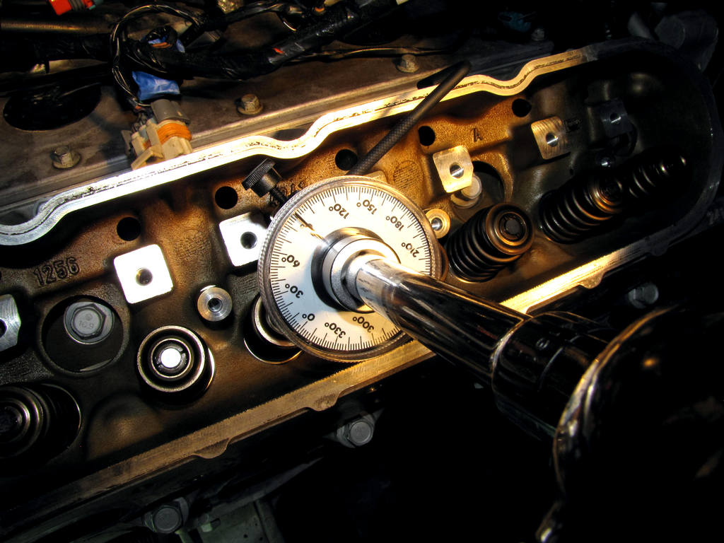
As for tools, the only fancy thing that you will need for this job is a angle torque meter. When tightening the head bolts, it calls for 3 different passes. The first 2 passes are done using the torque settings of your torque wrench. The 3rd pass is done using the torque angle meter. You DO NOT want to try and guess at this last pass. These meters come in all kinds of different styles (analog and digital), and cost any where from $8 to a few hundred. The one pictured below was only $8. It is not as easy to use on some bolt locations but it will get the job done accurately.
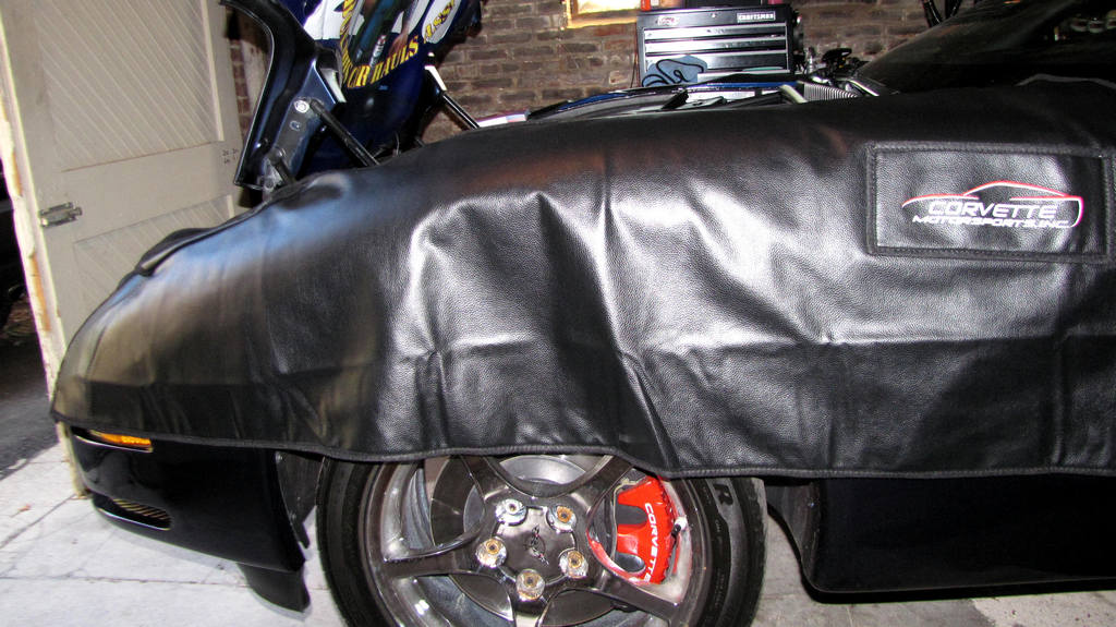
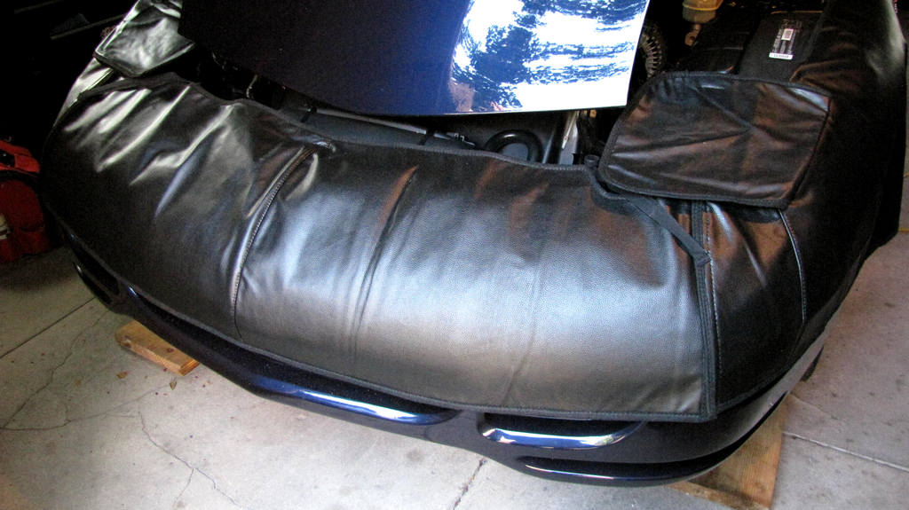
You should also have a quality fender cover for this job. I found this on on sale for around $100. They are normally twice that much.
On a scale of easy to hard, this was kinda daunting. It is mainly labor intensive and the fact that I did it in my garage with no help kinda made it a little more challenging. Using jack stands and laying under the car to remove and reinstall the exhaust all by myself is an experience that I do not care to experience again anytime soon. Other than that, the right cylinder head is a LOT easier than the left side. I am going to keep my directions just as the service manual instructs for a 2001 Corvette. Your engine may or may not differ slightly. In some places I will quote the manual, and then give a Layman's description of what the instructions are telling you to do (for people who find that working on cars can almost be rocket science ). With that said, let's get some! 
Cylinder Head Removal - Right Side
Step 1. Remove the right fuel rail cover.
If you don't understand this instruction, put your tools away and take the car to someone qualified.
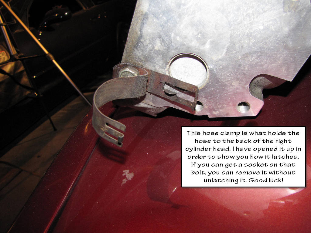
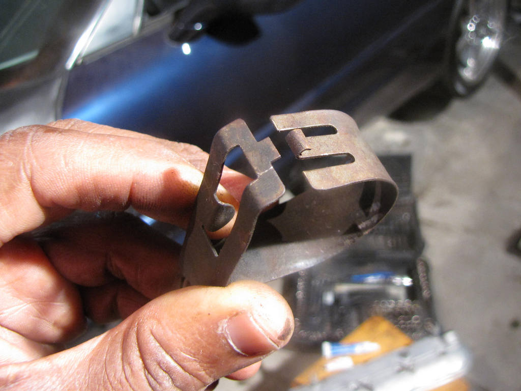
Step 2. Remove the secondary air injection (AIR) hose clamp.
Here's the hose clamp that they want you to remove. It is bolted to the back (next to the firewall) of the right cylinder head.
Step 3. Remove the AIR hose (1) from the check valve.
Here's a picture from the service manual.
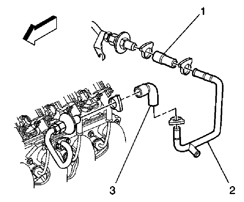
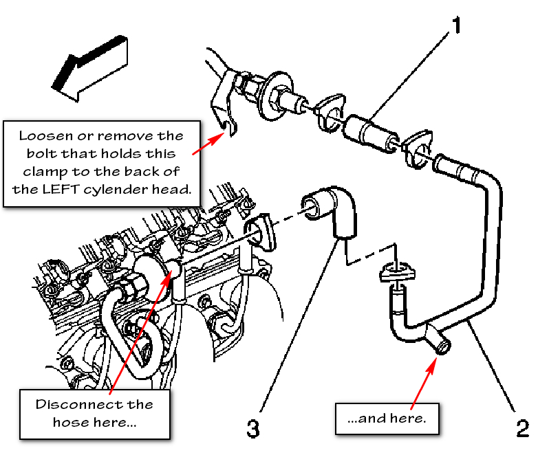
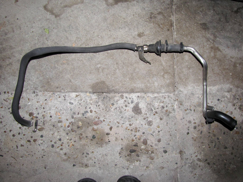
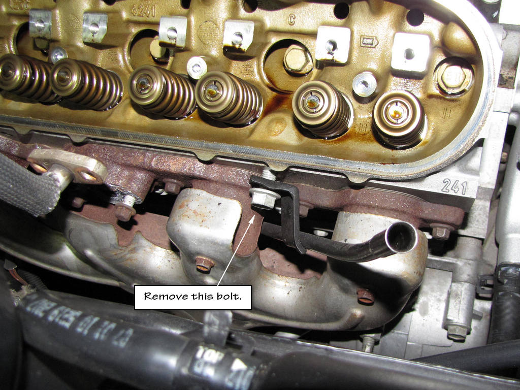
Now here's what I suggest that you do. After you have unclamped the AIR pipe from the back of the right cylinder head (or removed the clamp), remove the entire AIR pipe as one piece. See the picture below. Getting to that bolt behind the left cylinder head is an adventure.
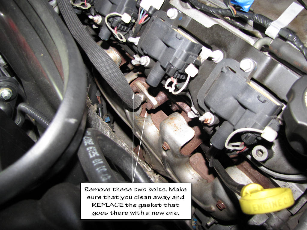
Step 4. Remove the AIR pipe bolts at the exhaust manifold.
AIR pipe removed.
If you are doing this the way that I have suggested, you can skip the next 4 steps because you have already completed them. I only post them so that you will have the steps specifically as they are listed in the service manual.
Step 5. Loosen, DO NOT remove the AIR pipe bolt at the rear of the left cylinder head.
Step 6. Slide the AIR pipe up and out from behind the bolt.
Step 7. Reposition the AIR pipe.
Step 8. Remove the AIR pipe gasket from the exhaust manifold.
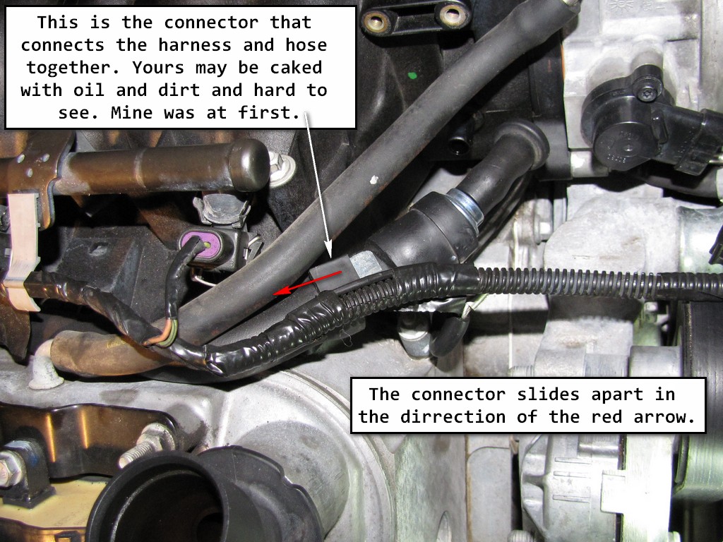
Step 9. Remove the throttle position (TP) sensor harness clip from the positive crankcase ventilation (PCV) tube.
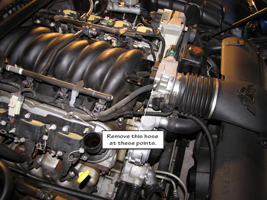
Step 10. Remove the PCV tube from the throttle body and rocker arm cover.
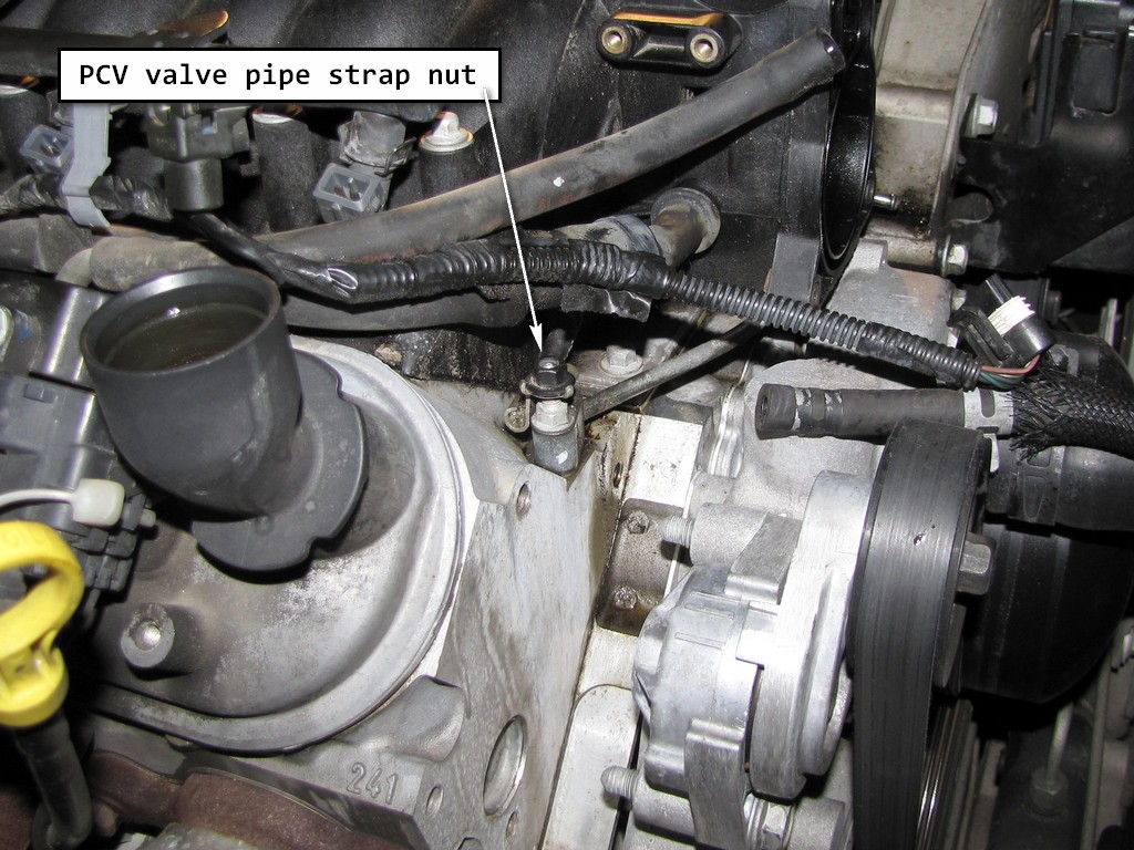
Step 11. If equipped with the regular production option (RPO) LS1 engine, remove the PCV valve pipe strap nut.
That would be this nut.
Step 12. Remove the PCV valve pipe from the right rocker arm cover and intake manifold.
Step 13. Disconnect the spark plug wires from the ignition coils and spark plugs.
Okay, the first time that I disconnected my wires, I tore the first one up. I spent a whole day trying to get out one spark plug. Now I can remove all 8 and the wires in about 30-40 minutes. How did I get so good? It's called motivation from experience. Each spark plug wire cost $26. It that doesn't motivate you to take your time, not get frustrated and tear up your wires, the cost of all 8 definitely will.
Step 14. Disconnect the ignition coil wire harness main electrical connector.
Step 15. Remove the ignition coil bracket studs.
One thing that you should notice that I do throughout this repair. When I unbolt, unclamp or unscrew something, I put that bolt, clamp, or screw back into the hole that it came out of if possible. That's because I could never remember where all these darn bolts and screws go. Remember that as you look at most of my pictures.
As for tools, the only fancy thing that you will need for this job is a angle torque meter. When tightening the head bolts, it calls for 3 different passes. The first 2 passes are done using the torque settings of your torque wrench. The 3rd pass is done using the torque angle meter. You DO NOT want to try and guess at this last pass. These meters come in all kinds of different styles (analog and digital), and cost any where from $8 to a few hundred. The one pictured below was only $8. It is not as easy to use on some bolt locations but it will get the job done accurately.
You should also have a quality fender cover for this job. I found this on on sale for around $100. They are normally twice that much.
On a scale of easy to hard, this was kinda daunting. It is mainly labor intensive and the fact that I did it in my garage with no help kinda made it a little more challenging. Using jack stands and laying under the car to remove and reinstall the exhaust all by myself is an experience that I do not care to experience again anytime soon. Other than that, the right cylinder head is a LOT easier than the left side. I am going to keep my directions just as the service manual instructs for a 2001 Corvette. Your engine may or may not differ slightly. In some places I will quote the manual, and then give a Layman's description of what the instructions are telling you to do (for people who find that working on cars can almost be rocket science
Cylinder Head Removal - Right Side
Step 1. Remove the right fuel rail cover.
If you don't understand this instruction, put your tools away and take the car to someone qualified.
Step 2. Remove the secondary air injection (AIR) hose clamp.
- Two things to note here. First, getting your hands back behind the the right cylinder head to try and do this is next to impossible. Secondly, it is much easier just to remove the entire AIR pipe as one piece instead of trying to disassemble it first, as the service manual wants you to do in step 3. In my writeup, you will notice that the AIR pipe is still on the car during my entire dis-assembly. I had to remove both the right and left cylinder heads before I could get the AIR pipe off the engine.
Here's the hose clamp that they want you to remove. It is bolted to the back (next to the firewall) of the right cylinder head.
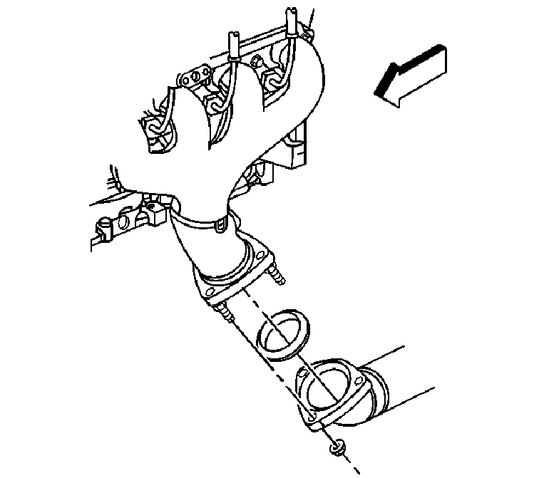
Step 3. Remove the AIR hose (1) from the check valve.
Here's a picture from the service manual.
Now here's what I suggest that you do. After you have unclamped the AIR pipe from the back of the right cylinder head (or removed the clamp), remove the entire AIR pipe as one piece. See the picture below. Getting to that bolt behind the left cylinder head is an adventure.
Step 4. Remove the AIR pipe bolts at the exhaust manifold.
AIR pipe removed.
If you are doing this the way that I have suggested, you can skip the next 4 steps because you have already completed them. I only post them so that you will have the steps specifically as they are listed in the service manual.
Step 5. Loosen, DO NOT remove the AIR pipe bolt at the rear of the left cylinder head.
Step 6. Slide the AIR pipe up and out from behind the bolt.
Step 7. Reposition the AIR pipe.
Step 8. Remove the AIR pipe gasket from the exhaust manifold.
Step 9. Remove the throttle position (TP) sensor harness clip from the positive crankcase ventilation (PCV) tube.
Step 10. Remove the PCV tube from the throttle body and rocker arm cover.
Step 11. If equipped with the regular production option (RPO) LS1 engine, remove the PCV valve pipe strap nut.
That would be this nut.
Step 12. Remove the PCV valve pipe from the right rocker arm cover and intake manifold.
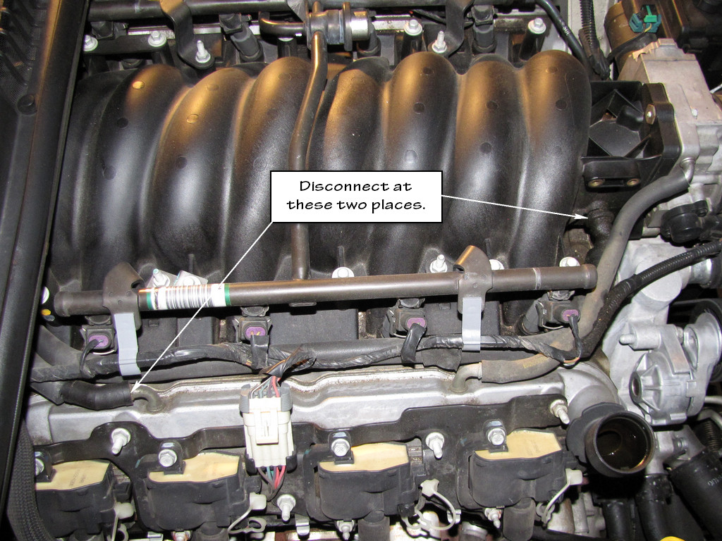
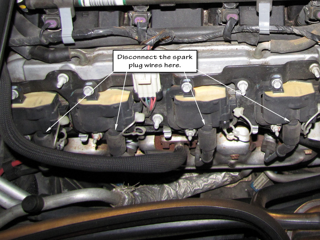
Step 13. Disconnect the spark plug wires from the ignition coils and spark plugs.
- Twist the spark plug wire boot 1/2 turn.
- Pull only on the boot in order to remove the wire from the ignition coil.
Okay, the first time that I disconnected my wires, I tore the first one up. I spent a whole day trying to get out one spark plug. Now I can remove all 8 and the wires in about 30-40 minutes. How did I get so good? It's called motivation from experience. Each spark plug wire cost $26. It that doesn't motivate you to take your time, not get frustrated and tear up your wires, the cost of all 8 definitely will.
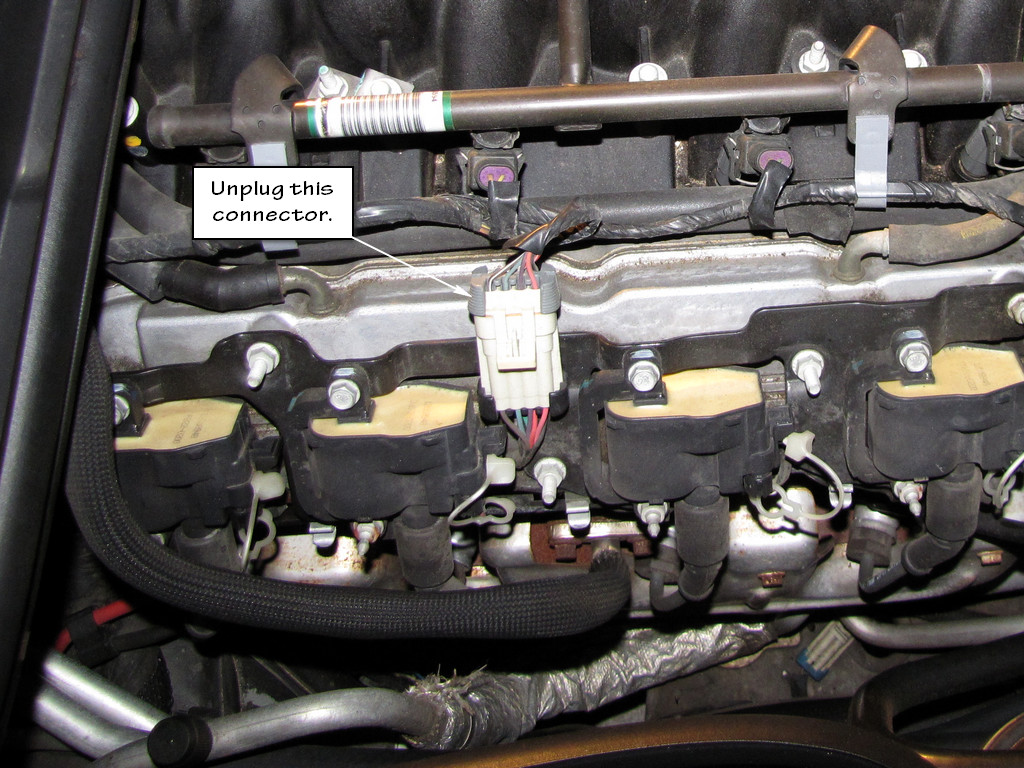
Step 14. Disconnect the ignition coil wire harness main electrical connector.
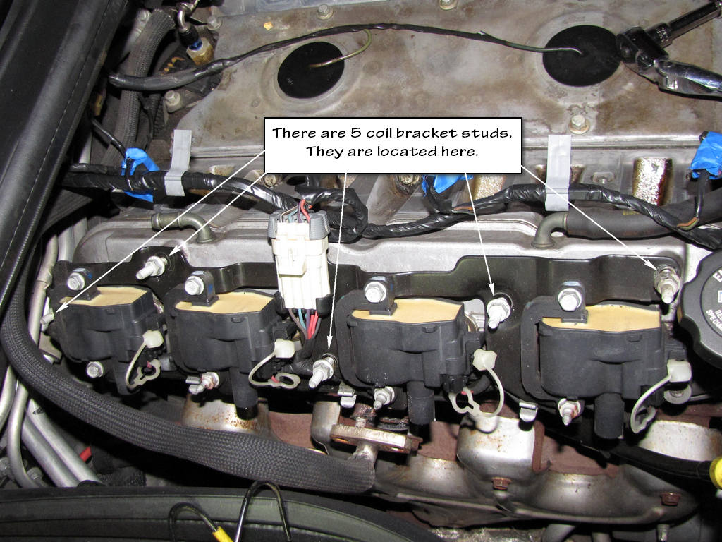
Step 15. Remove the ignition coil bracket studs.
Last edited by Junkman2008; 09-14-2012 at 05:49 AM.
 09-13-2012, 11:06 AM
#2
TECH Apprentice
Thread Starter
(con't)
Step 16. Remove the ignition coil bracket.
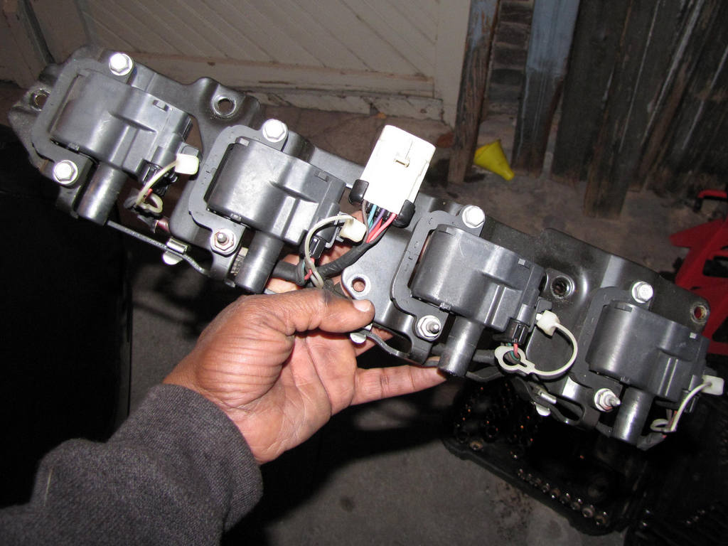
Step 17. Loosen the valve rocker arm cover bolts.
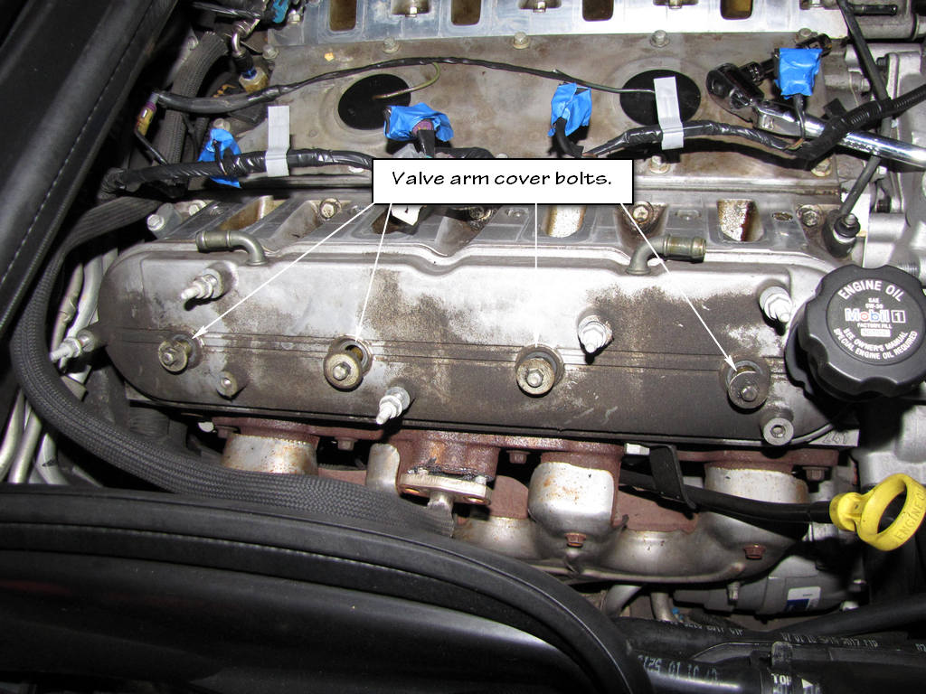
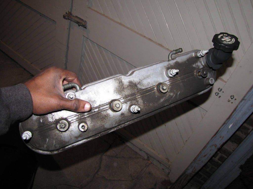
Step 18. Remove the valve rocker arm cover.
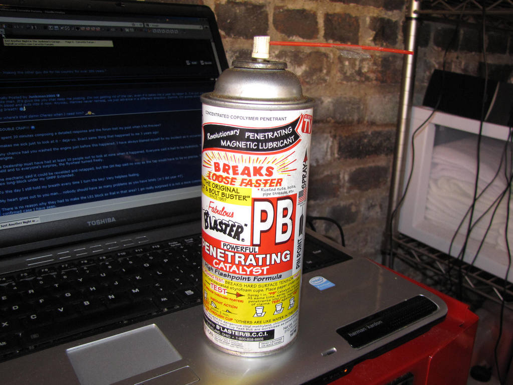
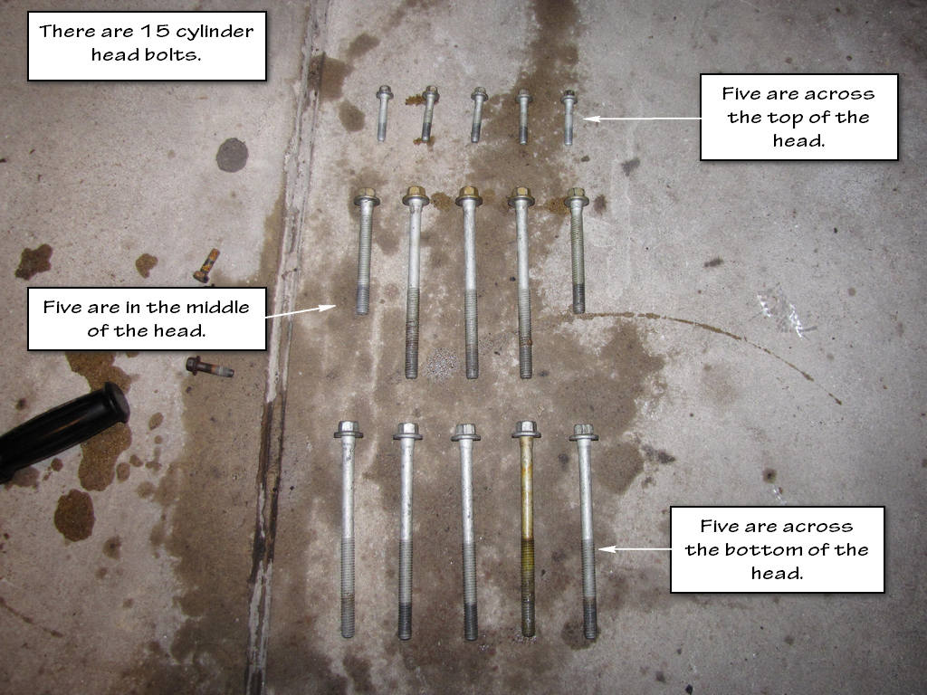
At this point, get out some PB Blaster and start soaking the cylinder head bolts. There are 15 of them (there are 5 that you can't see at this point just below the exhaust manifold). Those things will cause you to give birth to a trouser trout if you don't. They are tight like you wouldn't believe. When you go to reinstall them, you will quickly find out why they can't be reused and why they are such a PITA to remove.
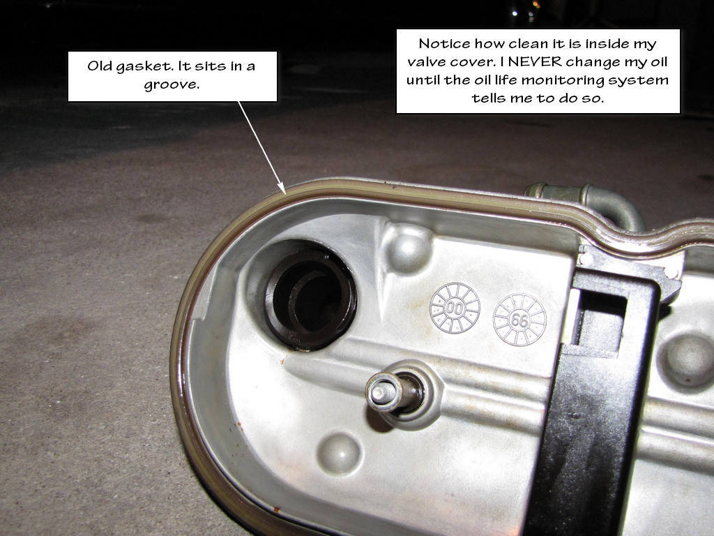
Step 19. Remove the gasket (1) from the rocker cover. Discard the OLD gasket.
This is a no brainer. DO NOT be a cheap azz and reuse the old gasket.
Step 20. Remove the oil fill cap from the oil fill tube.
This is not necessary unless you are replacing the oil fill tube for some reason.
Step 21. Remove the oil fill tube, IF REQUIRED.
This is not necessary unless you are replacing the oil fill tube for some reason.
Step 21. Discard the oil fill tube IF YOU DO REMOVE IT FOR SOME REASON. Do NOT reuse it if you remove it.
Step 22. Clean and inspect the valve rocker arm cover.
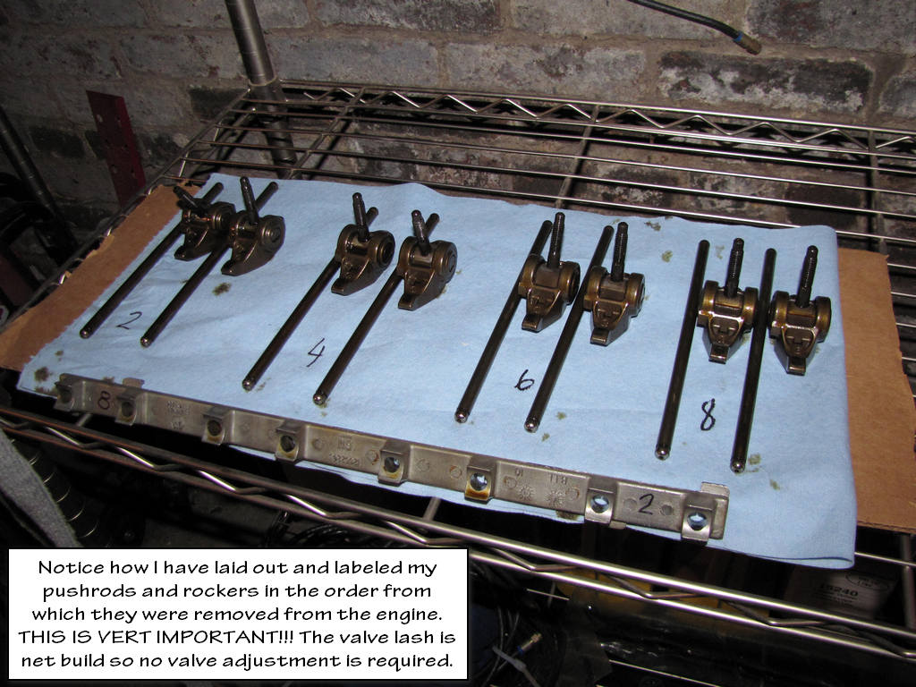
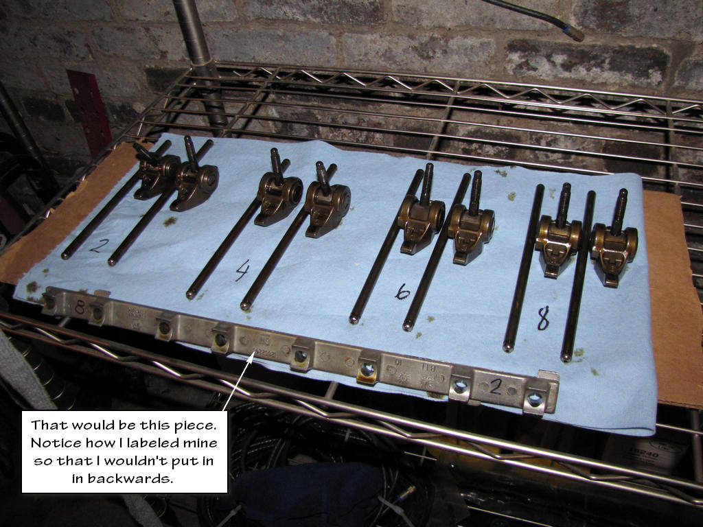
IMPORTANT!!!
Place the valve rocker arms, valve pushrods, and pivot support, in a rack so that they can be installed in the same location from which they were removed.
Step 23. Remove the valve rocker arm bolts.
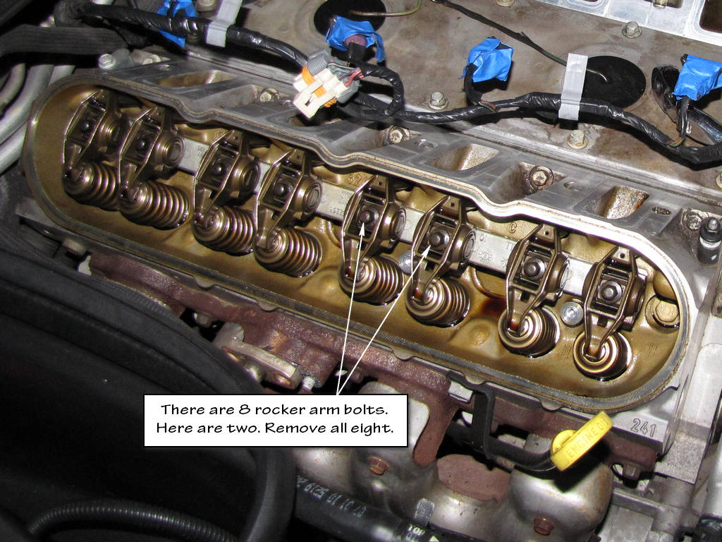
Step 24. Remove the valve rocker arms
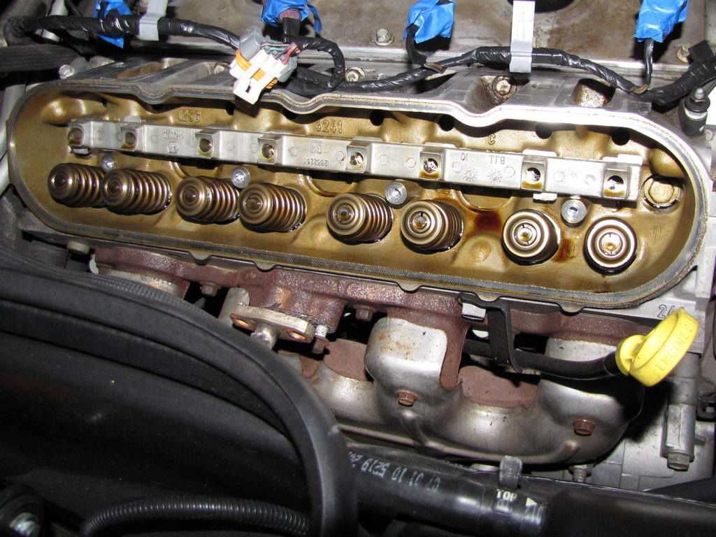
Step 25. Remove the valve rocker arm pivot support.
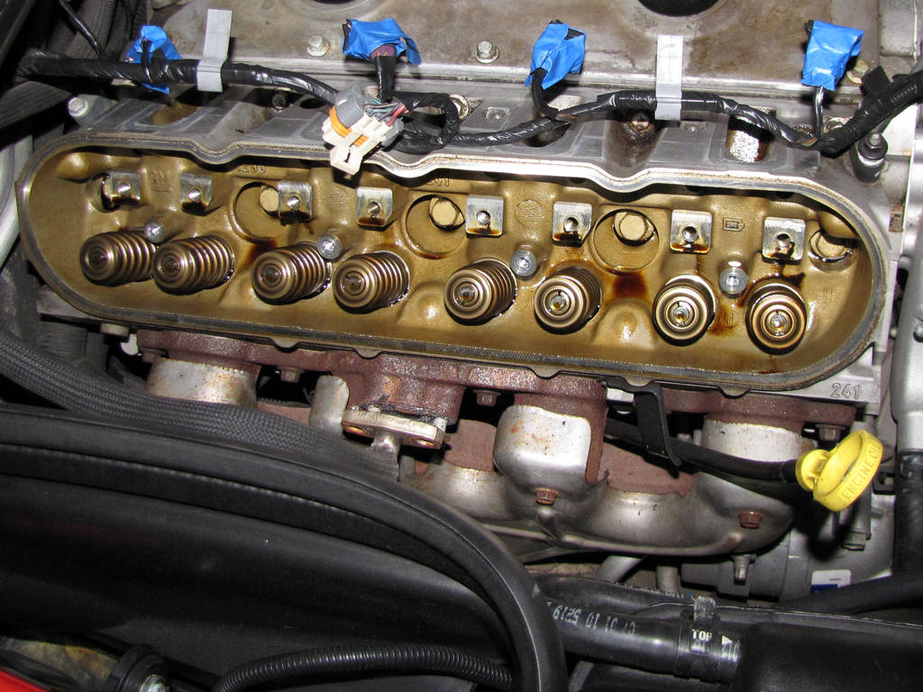
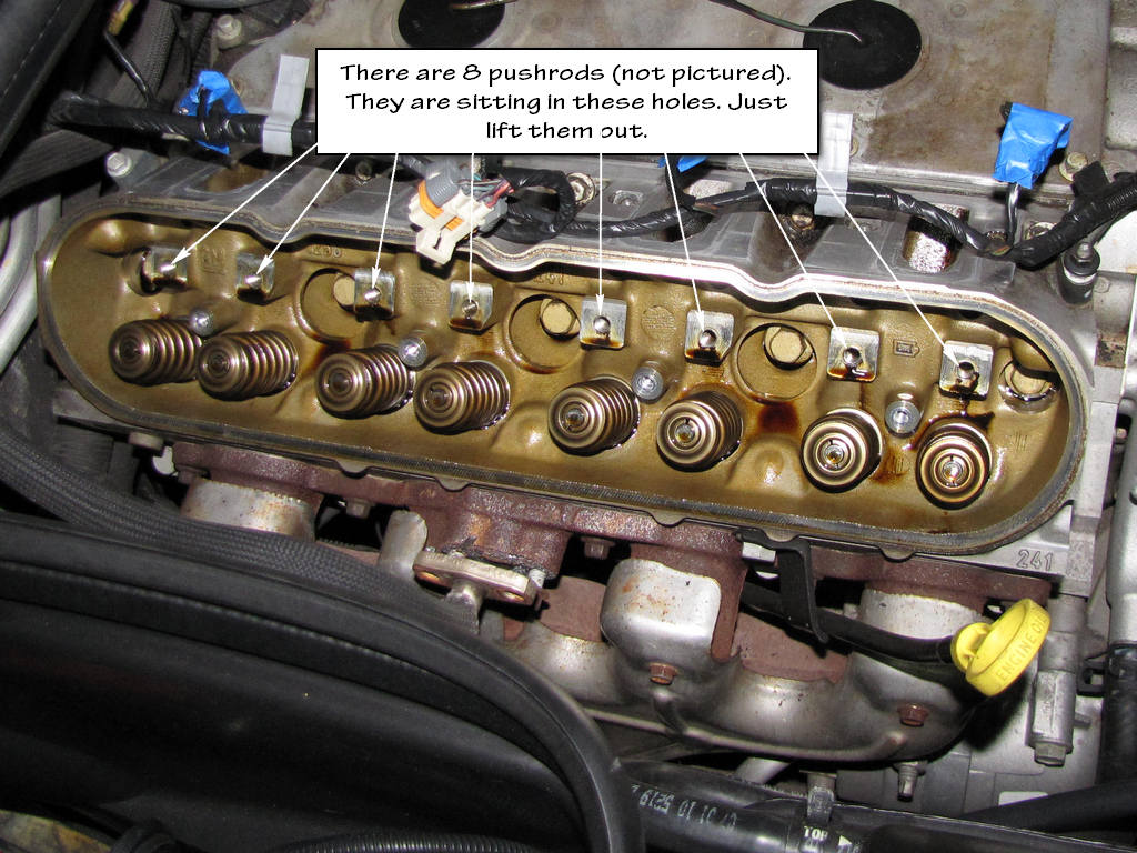
Step 26. Remove the pushrods.
Step 27. Clean and inspect the valve rocker arms and pushrods.
Important
Removal of the intake manifold is NOT required to service the coolant air bleed pipe, but is required to service the coolant air bleed pipe covers and/or gaskets.
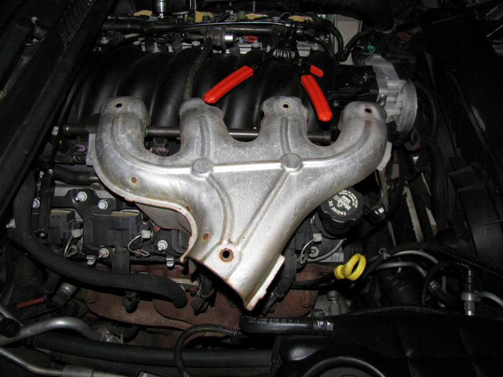
Step 28. Remove the intake manifold.
Instead of duplicating a writeup that I have already done, follow this link to my EOP sensor replacement DIY, in which the manifold removal is explained in detail. You will find that you may have already completed a few steps of that DIY at this point. Once the manifold has been removed, continue to step 29.
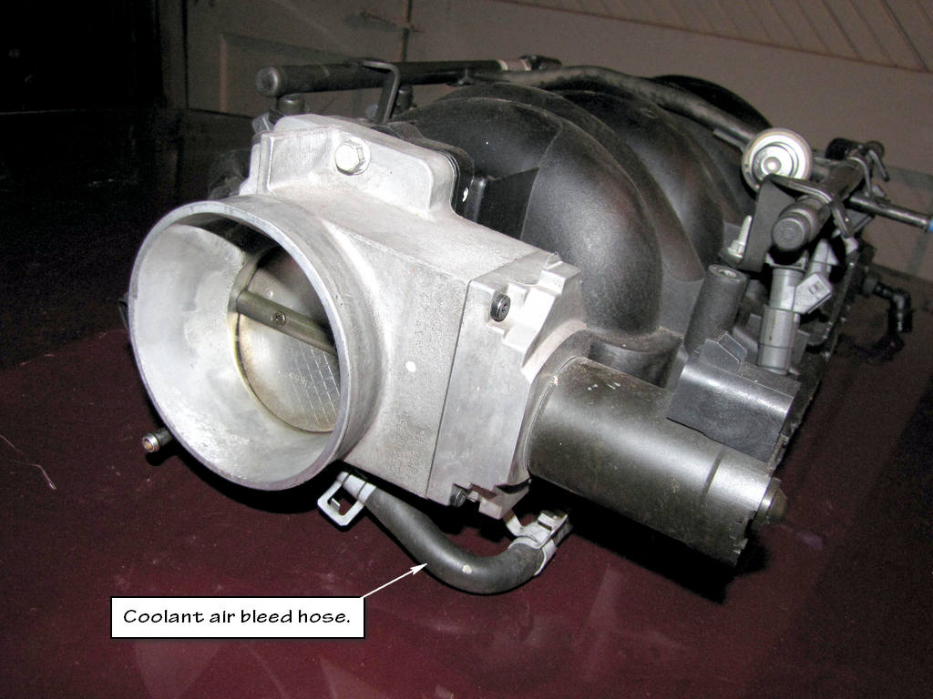
Step 29. Remove the coolant air bleed hose from the throttle body, if required.
This hose should still be attached to the throttle body if you followed my EOP sensor writeup. Leave it attached there.
For the next 2 steps, see the picture below.
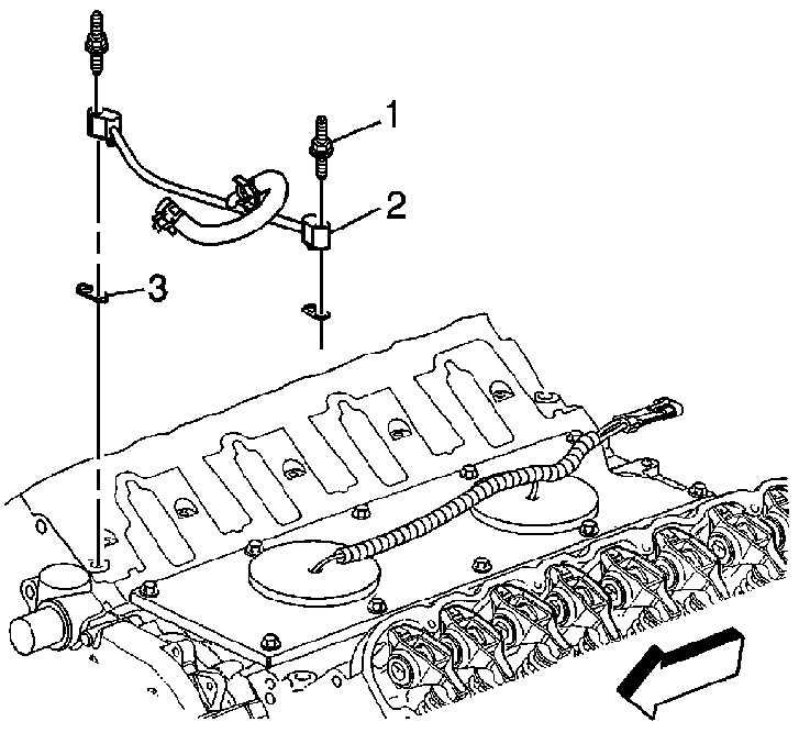
Step 30. Remove the coolant air bleed pipe studs (1).
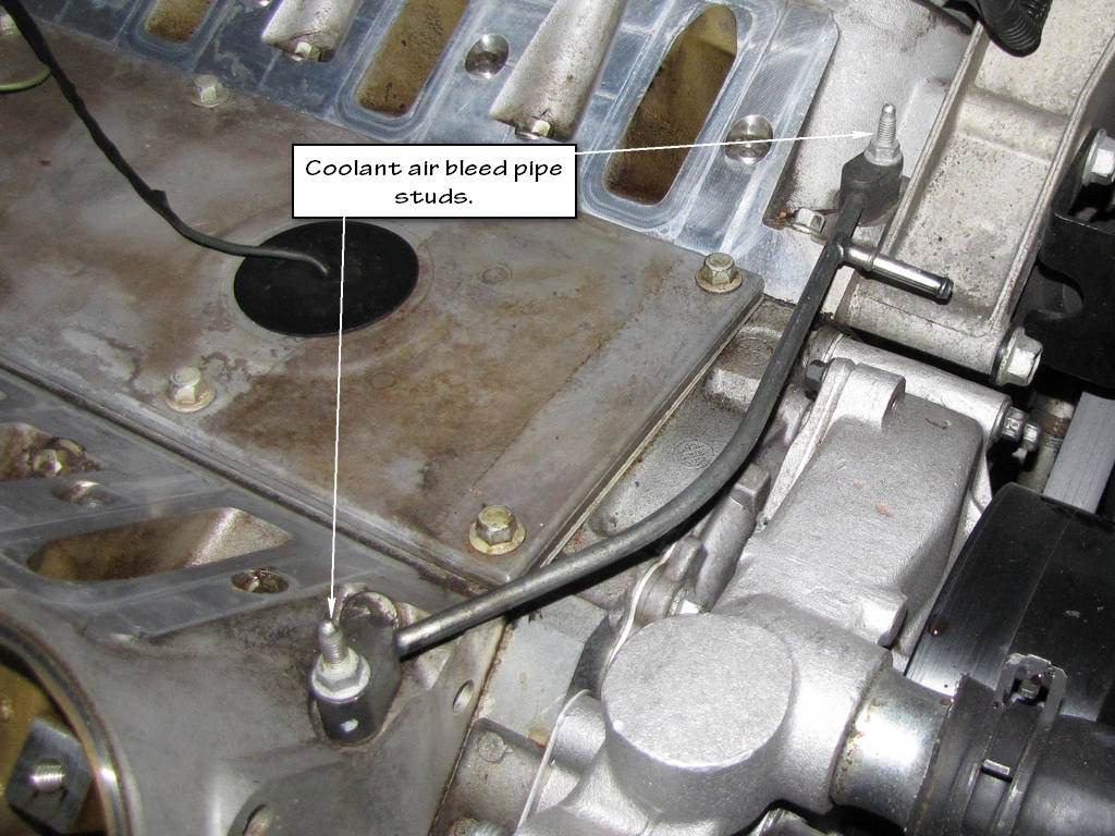
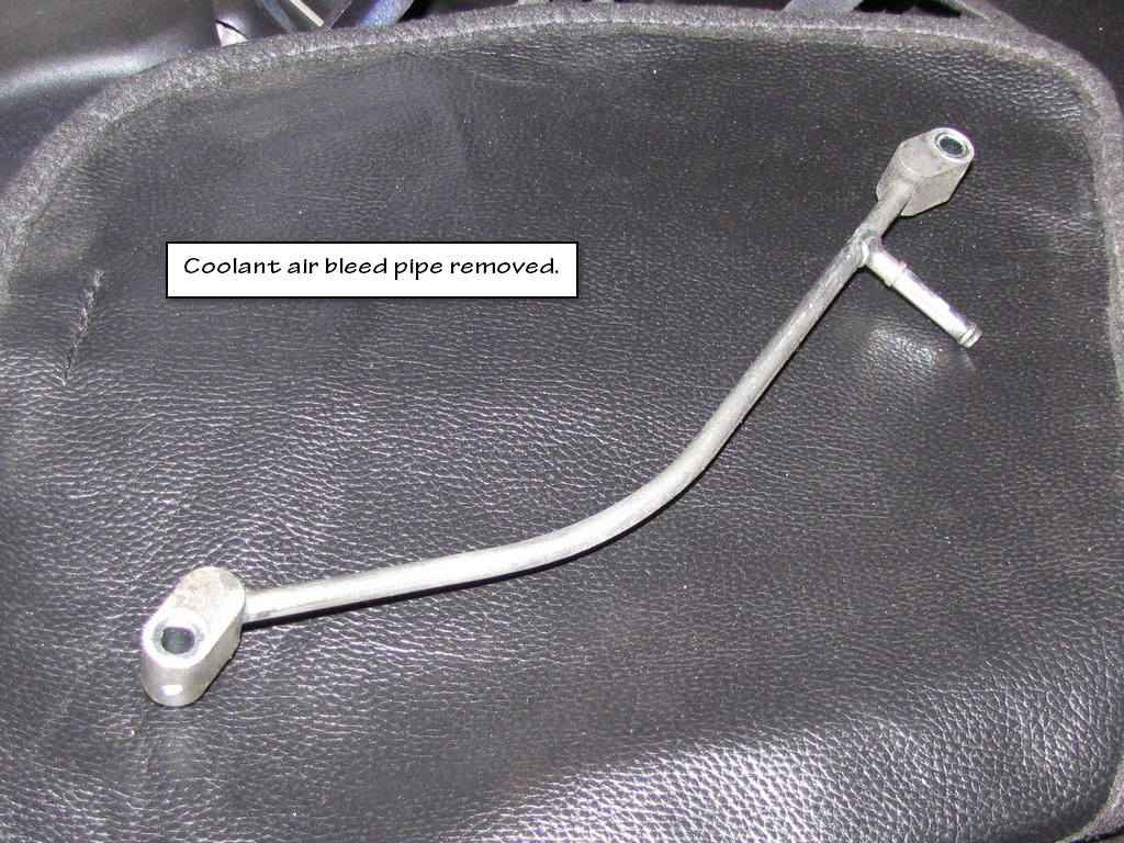
Step 31. Remove the coolant air bleed pipe (2) with gaskets (3).
(For the next 2 steps, see the picture below. Note that I cannot remember a need to perform the next 2 steps as nothing is connected to these points at the back of the engine. Again, that's what I recall. I only include them to keep my instructions just as the service manual has them written.
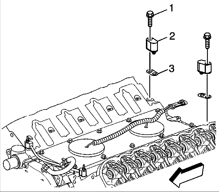
Step 32. Remove the coolant air bleed pipe cover bolts (1), if required.
Step 33. Remove the coolant air bleed pipe covers (2) with gaskets (3), if required.
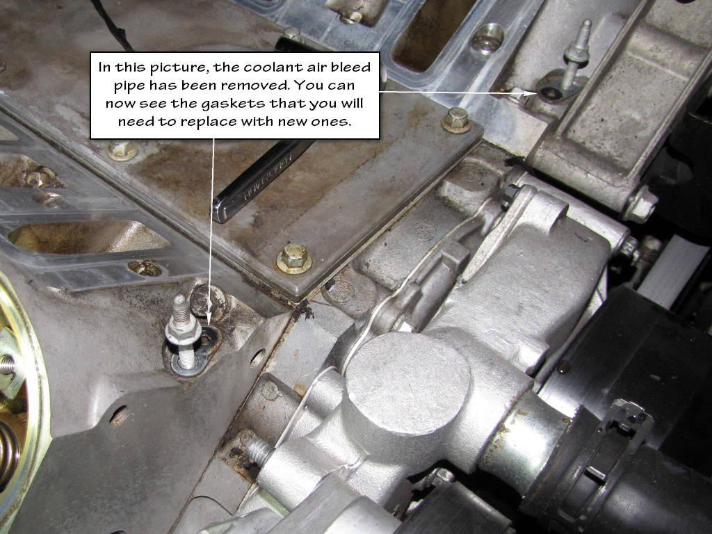
Step 34. Remove the gaskets from the coolant air bleed pipe and covers. Discard the gaskets.
You may get the idea that you can reuse these gaskets. Trust me, YOU CAN'T. Those tiny little gaskets can cause one big ol' leak. If you break the seal, REPLACE THEM.
Step 16. Remove the ignition coil bracket.
Step 17. Loosen the valve rocker arm cover bolts.
Step 18. Remove the valve rocker arm cover.
At this point, get out some PB Blaster and start soaking the cylinder head bolts. There are 15 of them (there are 5 that you can't see at this point just below the exhaust manifold). Those things will cause you to give birth to a trouser trout if you don't. They are tight like you wouldn't believe. When you go to reinstall them, you will quickly find out why they can't be reused and why they are such a PITA to remove.
Step 19. Remove the gasket (1) from the rocker cover. Discard the OLD gasket.
This is a no brainer. DO NOT be a cheap azz and reuse the old gasket.
Step 20. Remove the oil fill cap from the oil fill tube.
This is not necessary unless you are replacing the oil fill tube for some reason.
Step 21. Remove the oil fill tube, IF REQUIRED.
This is not necessary unless you are replacing the oil fill tube for some reason.
Step 21. Discard the oil fill tube IF YOU DO REMOVE IT FOR SOME REASON. Do NOT reuse it if you remove it.
Step 22. Clean and inspect the valve rocker arm cover.
IMPORTANT!!!
Place the valve rocker arms, valve pushrods, and pivot support, in a rack so that they can be installed in the same location from which they were removed.
Step 23. Remove the valve rocker arm bolts.
Step 24. Remove the valve rocker arms
Step 25. Remove the valve rocker arm pivot support.
Step 26. Remove the pushrods.
Step 27. Clean and inspect the valve rocker arms and pushrods.
Important
Removal of the intake manifold is NOT required to service the coolant air bleed pipe, but is required to service the coolant air bleed pipe covers and/or gaskets.
Step 28. Remove the intake manifold.
Instead of duplicating a writeup that I have already done, follow this link to my EOP sensor replacement DIY, in which the manifold removal is explained in detail. You will find that you may have already completed a few steps of that DIY at this point. Once the manifold has been removed, continue to step 29.
Step 29. Remove the coolant air bleed hose from the throttle body, if required.
This hose should still be attached to the throttle body if you followed my EOP sensor writeup. Leave it attached there.
For the next 2 steps, see the picture below.
Step 30. Remove the coolant air bleed pipe studs (1).
Step 31. Remove the coolant air bleed pipe (2) with gaskets (3).
(For the next 2 steps, see the picture below. Note that I cannot remember a need to perform the next 2 steps as nothing is connected to these points at the back of the engine. Again, that's what I recall. I only include them to keep my instructions just as the service manual has them written.
Step 32. Remove the coolant air bleed pipe cover bolts (1), if required.
Step 33. Remove the coolant air bleed pipe covers (2) with gaskets (3), if required.
Step 34. Remove the gaskets from the coolant air bleed pipe and covers. Discard the gaskets.
You may get the idea that you can reuse these gaskets. Trust me, YOU CAN'T. Those tiny little gaskets can cause one big ol' leak. If you break the seal, REPLACE THEM.
Last edited by Junkman2008; 09-13-2012 at 11:24 AM.
09-13-2012, 11:06 AM
#3
TECH Apprentice
Thread Starter
(con't)
Step 35. Remove the coolant air bleed hose (2) from the pipe (1).
That hose should still be connected to the throttle body from when you removed the manifold.
Step 36. Clean and inspect the coolant air bleed pipe.
Make sure that the surfaces of the pipe that will touch the gaskets are spotless. You want a solid connection there. Also, pay close attention to the way the gaskets are orientated. Don't install them backwards.
You are now ready to spend some time UNDER the car. Get your safety glasses ready. You don't want crap falling into your eyes.
Step 37. Raise and suitably support the vehicle.
In my EOP sensor DIY, I explain how I raise my vehicle. Remember, there are only 8 points that you can use to raise your vehicle. These locations are in your owner's manual.
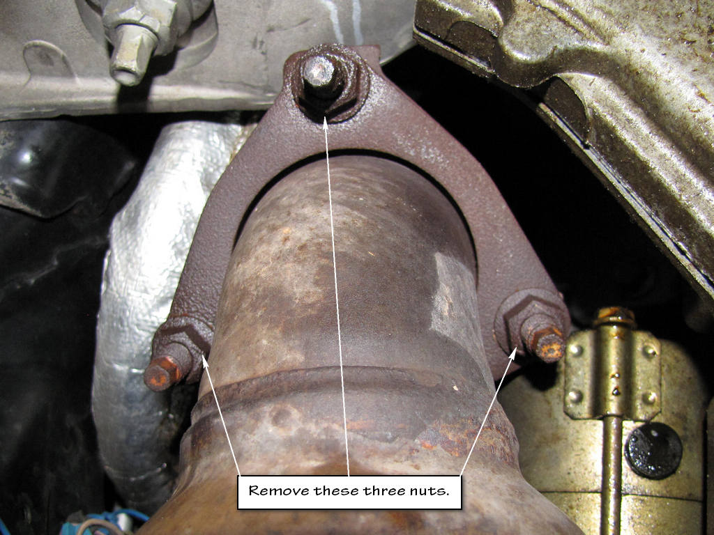
Step 38. Remove the exhaust manifold nuts. (left side shown, right side similar)
These bolts are also a candidate for some PB Blaster. "Don't bust your knuckles, bust your nuts with PB Blaster!" :laughing:
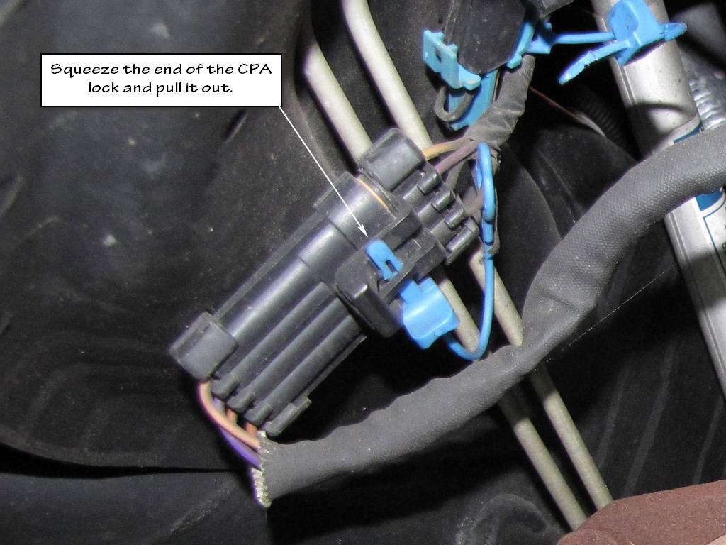
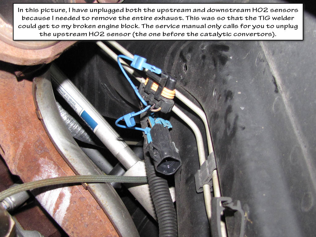
Step 39. Remove the connector position assurance (CPA) lock.
I must have read this instruction 20 times before I figured out what the CPA locks were! The CPA locks are the blue things that ensure that the heated oxygen sensor connectors stay connected. Some guys will get frustrated and cut them. I took the time to squeeze the ends of them with some needle nose pliers and unplug them.
Step 38. Disconnect the oxygen sensor electrical connector.
Important Notice!!!
Handle the oxygen sensors carefully in order to prevent damage to the component. Keep the electrical connector and the exhaust inlet end free of contaminants. Do not use cleaning solvents on the sensor. Do not drop or mishandle the sensor.
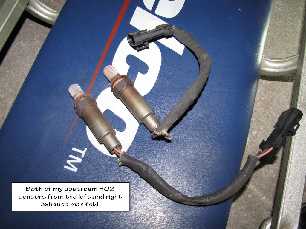
Step 39. Remove the oxygen sensor.
Step 40. Lower the vehicle.
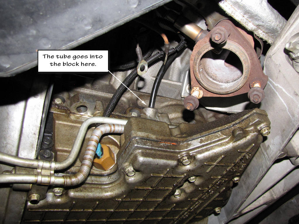
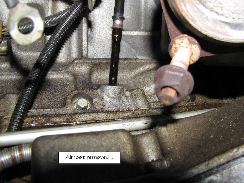
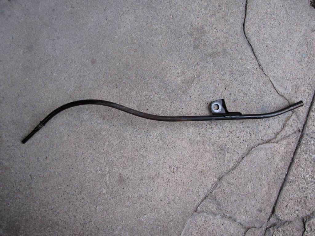
Step 41. Remove the oil level indicator tube.
Then gently wiggle the oil level indicator tube while lifting upward.
Notice
Allow the engine to cool before removing the spark plugs. Attempting to remove the spark plugs from a hot engine may cause the plug threads to seize, causing damage to cylinder head threads.
Notice
Clean the spark plug recess area before removing the spark plug. Failure to do so could result in engine damage because of dirt or foreign material entering the cylinder head, or by the contamination of the cylinder head threads. The contaminated threads may prevent the proper seating of the new plug. Use a thread chaser to clean the threads of any contamination.
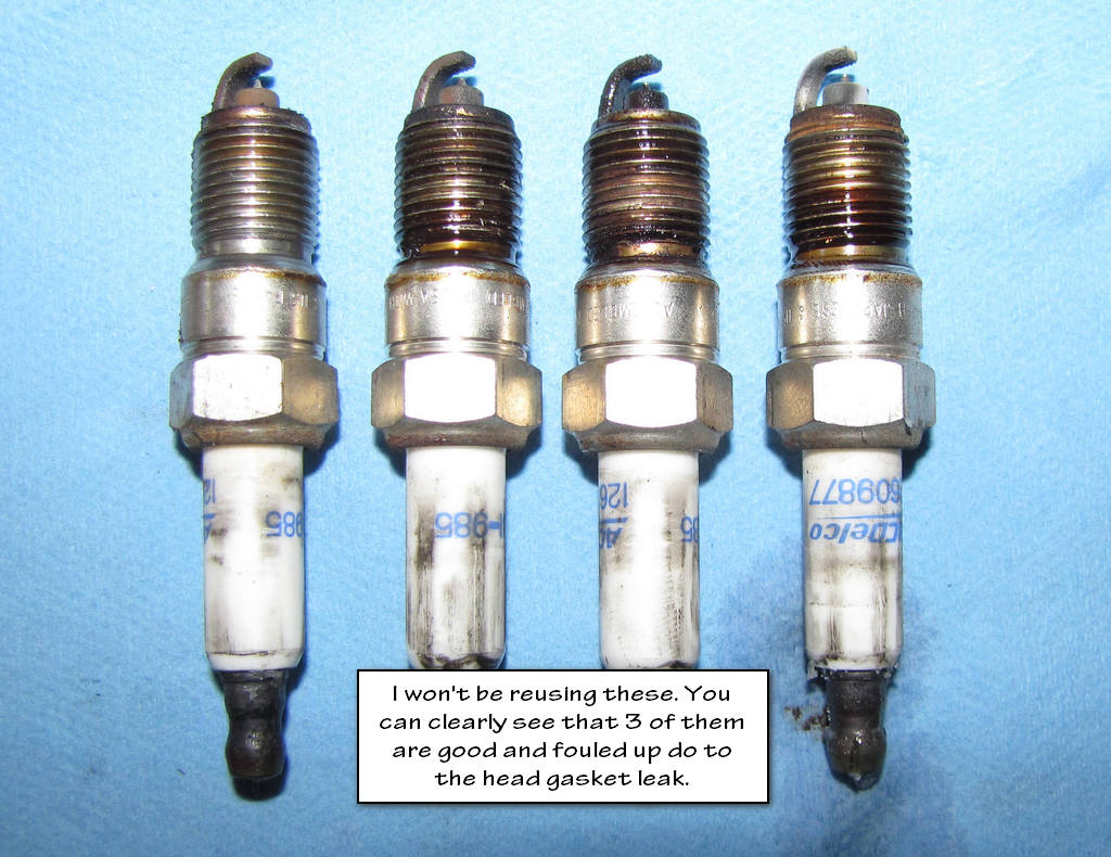
Step 42. Remove the spark plugs.
The best advice that I can give you here is to just be patient. Once you've removed your spark plugs for the first time, it gets SIGNIFICANTLY easier to do it again from that point forward.
Step 43. Remove the exhaust manifold bolts.
If you think that you have removed all the exhaust manifold bolts and the thing still feels like it is stuck to the engine block, then you've missed a bolt somewhere. Double check to make sure you've removed them all. One bolt likes to hide. Although the manual doesn't say to do this, I replaced all of mine. When you see how rusty they are, you'll want to do the same. That's the last bolt that I want to break during my reassembly.
Step 44. Remove the exhaust manifold, and old gasket. Discard the gasket.
Step 45. If necessary, remove the exhaust manifold heat shield bolts and shield.
I seem to always find it necessary to get that damn thing out of the way. It is NOT a fun task.
Important
The cylinder head bolts are NOT reusable!
Don't, in your wildest dreams think about reusing those bolts!
Step 46. Remove the cylinder head bolts.
There are 15 bolts. If you did not soak yours in PB Blaster, I hope you're wearing your Depends. :laughing:
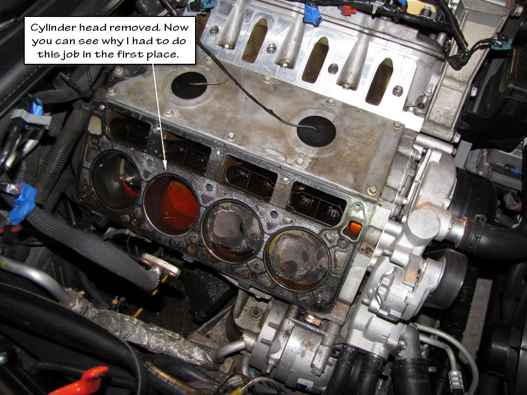
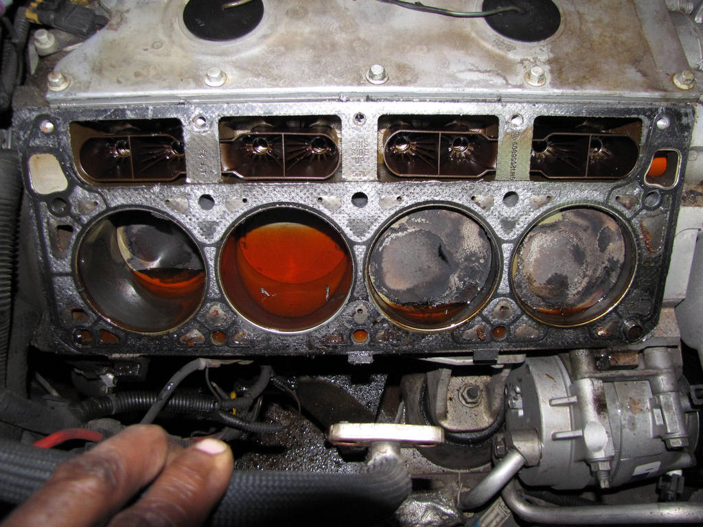
Step 47. Remove the cylinder head. :partyon:
Step 48. Remove the cylinder head gasket.
Step 49. Discard the gasket.
Step 50. Discard the cylinder head bolts.
Step 35. Remove the coolant air bleed hose (2) from the pipe (1).
That hose should still be connected to the throttle body from when you removed the manifold.
Step 36. Clean and inspect the coolant air bleed pipe.
Make sure that the surfaces of the pipe that will touch the gaskets are spotless. You want a solid connection there. Also, pay close attention to the way the gaskets are orientated. Don't install them backwards.
You are now ready to spend some time UNDER the car. Get your safety glasses ready. You don't want crap falling into your eyes.
Step 37. Raise and suitably support the vehicle.
In my EOP sensor DIY, I explain how I raise my vehicle. Remember, there are only 8 points that you can use to raise your vehicle. These locations are in your owner's manual.
Step 38. Remove the exhaust manifold nuts. (left side shown, right side similar)
These bolts are also a candidate for some PB Blaster. "Don't bust your knuckles, bust your nuts with PB Blaster!" :laughing:
Step 39. Remove the connector position assurance (CPA) lock.
I must have read this instruction 20 times before I figured out what the CPA locks were! The CPA locks are the blue things that ensure that the heated oxygen sensor connectors stay connected. Some guys will get frustrated and cut them. I took the time to squeeze the ends of them with some needle nose pliers and unplug them.
Step 38. Disconnect the oxygen sensor electrical connector.
Important Notice!!!
Handle the oxygen sensors carefully in order to prevent damage to the component. Keep the electrical connector and the exhaust inlet end free of contaminants. Do not use cleaning solvents on the sensor. Do not drop or mishandle the sensor.
Step 39. Remove the oxygen sensor.
Step 40. Lower the vehicle.
Step 41. Remove the oil level indicator tube.
Then gently wiggle the oil level indicator tube while lifting upward.
Notice
Allow the engine to cool before removing the spark plugs. Attempting to remove the spark plugs from a hot engine may cause the plug threads to seize, causing damage to cylinder head threads.
Notice
Clean the spark plug recess area before removing the spark plug. Failure to do so could result in engine damage because of dirt or foreign material entering the cylinder head, or by the contamination of the cylinder head threads. The contaminated threads may prevent the proper seating of the new plug. Use a thread chaser to clean the threads of any contamination.
Step 42. Remove the spark plugs.
The best advice that I can give you here is to just be patient. Once you've removed your spark plugs for the first time, it gets SIGNIFICANTLY easier to do it again from that point forward.
Step 43. Remove the exhaust manifold bolts.
If you think that you have removed all the exhaust manifold bolts and the thing still feels like it is stuck to the engine block, then you've missed a bolt somewhere. Double check to make sure you've removed them all. One bolt likes to hide. Although the manual doesn't say to do this, I replaced all of mine. When you see how rusty they are, you'll want to do the same. That's the last bolt that I want to break during my reassembly.
Step 44. Remove the exhaust manifold, and old gasket. Discard the gasket.
Step 45. If necessary, remove the exhaust manifold heat shield bolts and shield.
I seem to always find it necessary to get that damn thing out of the way. It is NOT a fun task.
Important
The cylinder head bolts are NOT reusable!
Don't, in your wildest dreams think about reusing those bolts!
Step 46. Remove the cylinder head bolts.
There are 15 bolts. If you did not soak yours in PB Blaster, I hope you're wearing your Depends. :laughing:
Step 47. Remove the cylinder head. :partyon:
Step 48. Remove the cylinder head gasket.
Step 49. Discard the gasket.
Step 50. Discard the cylinder head bolts.
Last edited by Junkman2008; 09-13-2012 at 11:14 AM.
09-13-2012, 11:07 AM
#4
TECH Apprentice
Thread Starter
Re-installation
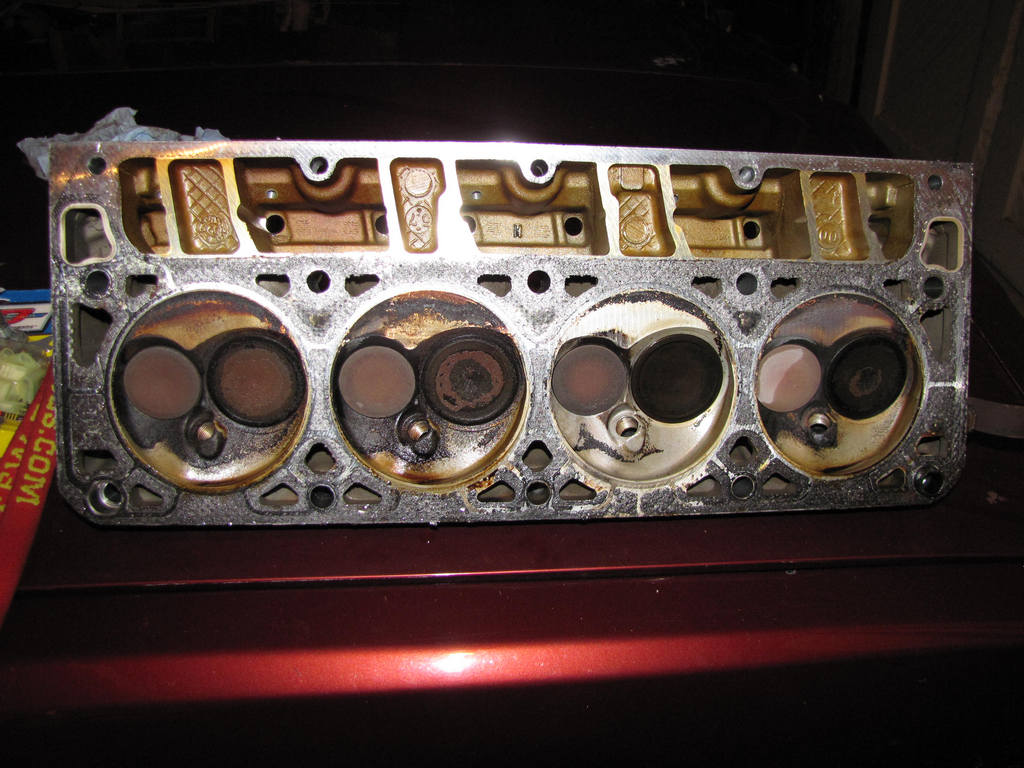
Before you install your cylinder heads, you are going to want to have them checked out. They may be slightly warped, especially if your engine overheated at some point. The cylinder heads may need to be shaved to ensure that they are perfectly flat. DO NOT skip this step. Have your heads inspected and machined if necessary by a quality shop. I paid about $180 to have my inspected and shaved. They removed .0006 (thousandths) of an inch to make them perfect. Not much at all and that did not change any characteristics of my motor.
Important
Do not reuse the cylinder head bolts. Install NEW cylinder head bolts during assembly.
Do not use any type of sealant on the cylinder head gasket (unless specified).
The cylinder head gasket must be installed in the proper direction and position.
Caution
Wear safety glasses in order to avoid eye damage.
Notice
Clean all dirt, debris, and coolant from the engine block cylinder head bolt holes. Failure to remove all foreign material may result in damaged threads, improperly tightened fasteners or damage to components.
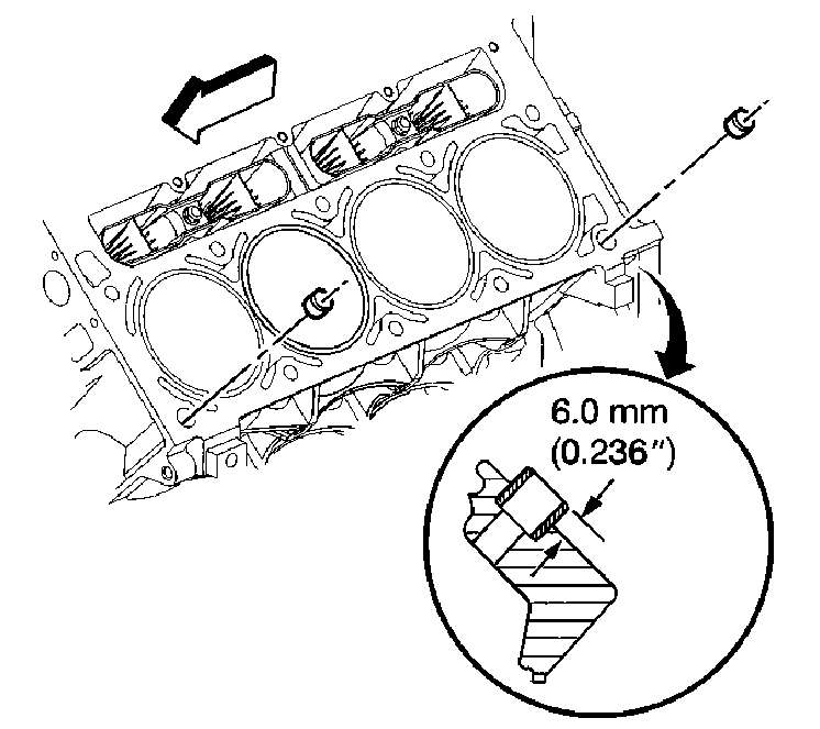
Here's a picture from the service manual which shows the cylinder head locating pins and how they are supposed to be inserted into the block (just in case yours are removed or come out).
Step 1. Clean the engine block head bolt holes (if required). Thread repair tool J 42385-107 may be used to clean the threads of the old threadlocking material.
I got myself a spiral wire brush and used brake cleaning fluid to clean out my bolt holes. Then I used my fancy vacuum cleaner with a small tube attachment to suck everything out of the holes. Some people will use their old bolts to clean the holes by running them in and out of the bolt holes. It is imperative that you get EVERYTHING out of those bolt holes before reassembly. Failure to do so could cause another leak to develop. The next steps are the way the service manual has you do it. Make sure you are wearing your safety glasses if you do it this way!
Step 2. Spray cleaner GM U.S. P/N 12346139, P/N 12377981, Canada P/N 10953463, or equivalent into the hole.
Step 3. Clean the cylinder head holes with compressed air
Step 4. Check the cylinder head locating pins for proper installation.
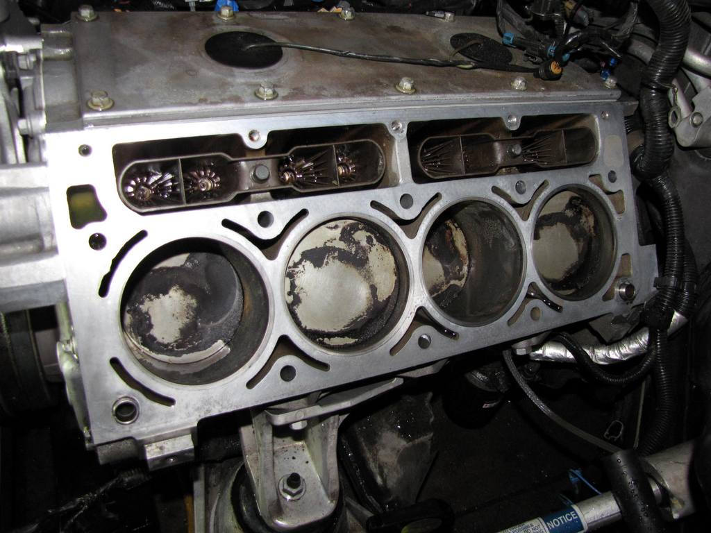
Before performing the next step, make sure that you clean ALL of the old gasket off the engine block. Failure to do so will result in another leak! Here's what mine looked like after I cleaned it. It's the driver's side but you get the drift. I used a soft scrubby pad and some Simple Green. DO NOT spray Simple Green directly on the engine. Spray it on the soft scrubby sponge and use that to clean the surface. If Simple Green is left sitting on aluminum long enough, it can cause pitting and it will eat at your gaskets.
Step 5. Install the NEW cylinder head gasket onto the locating pins.
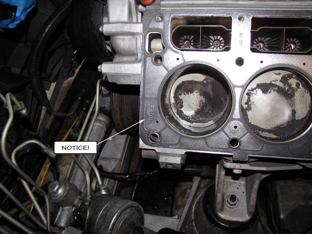
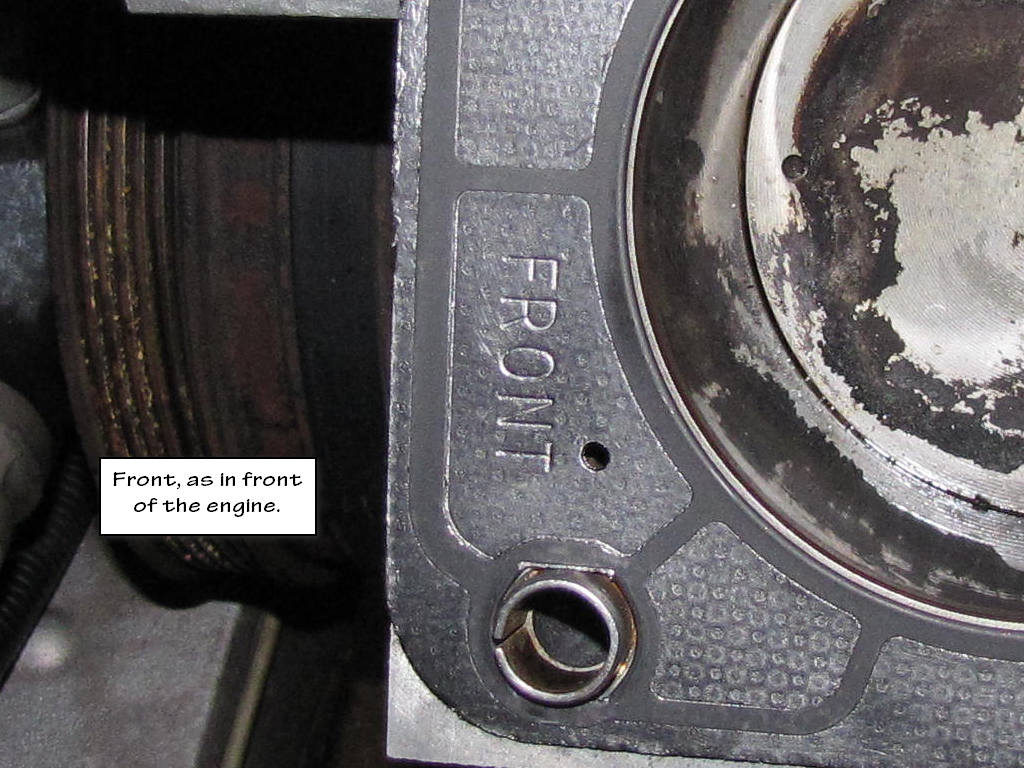
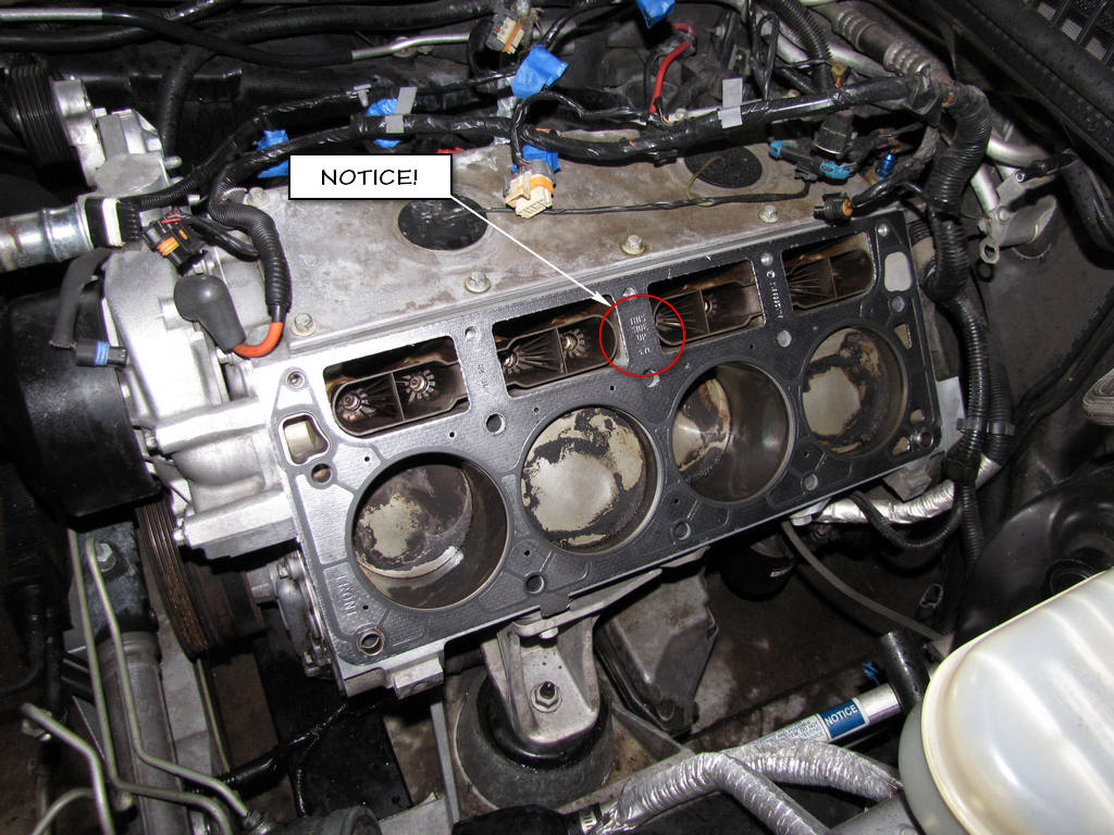
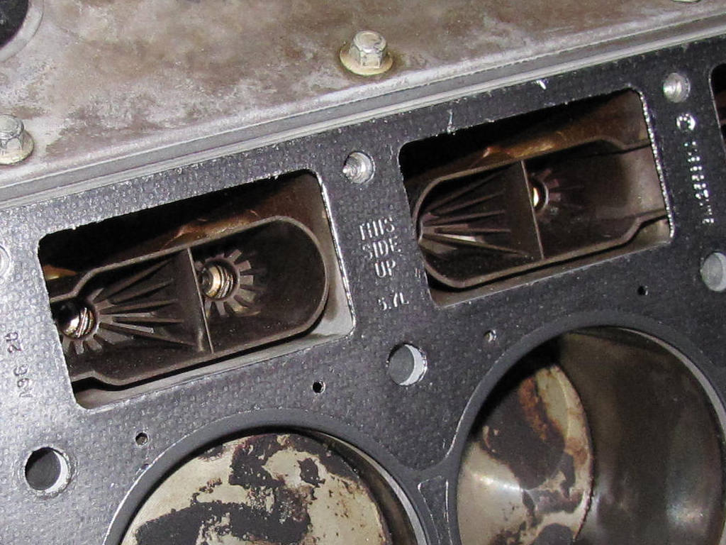
Pay special attention to the orientation of the new gasket and make sure that you install the correct side facing upward! See the pictures below. These are of the driver's side but the wording on the gaskets are what you need to pay special attention to.
Important
When properly installed, the tab on the right cylinder head gasket will be located left of center, or closer to the front of the engine, and the words "This Side Up", and the engine displacement, will be visible.
Step 6. Inspect the gasket for proper installation.
Step 7. Install the cylinder head onto the locating pins and the gasket.
Be careful not to drop the heads and gouge anything!
Step 8. Install NEW cylinder head bolts.
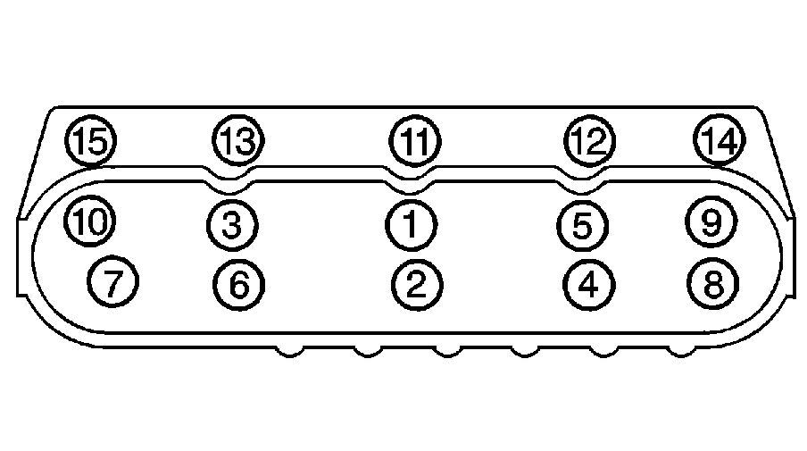
Hand tighten them into their respective holes. Here's the layout again if you have forgotten.

Step 9. Tighten the cylinder head bolts.
Okay, here comes the fun part!!!
If you have never used an angle torque gauge, WATCH THIS VIDEO! It not only explains how to use the thing, it also explains why you are tightening the bolts to the degree that you are, and why you cannot reuse your old bolts. I found this video to be invaluable given the amount of information contained within it. Also, the guy in the video explains everything so well that even I understood it. Remember, I'm the guy who didn't even know what a head gasket was when I started this repair!
Notice
Use the correct fastener in the correct location. Replacement fasteners must be the correct part number for that application. Fasteners requiring replacement or fasteners requiring the use of thread locking compound or sealant are identified in the service procedure. Do not use paints, lubricants, or corrosion inhibitors on fasteners or fastener joint surfaces unless specified. These coatings affect fastener torque and joint clamping force and may damage the fastener. Use the correct tightening sequence and specifications when installing fasteners in order to avoid damage to parts and systems.
Here is your torque sequence:
Here are your torque values:
Step 10. Install the wiring harness to the clip at the rear of the cylinder head.
Step 11. Position the oil level indicator tube into place.
Step 12. Install the oil level indicator tube bolt. Tighten the oil level indicator tube bolt to 25 N�m (18 lb ft).
Install the Exhaust Manifold
Important
Tighten the exhaust manifold bolts as specified in the service procedure. Improperly installed and/or leaking exhaust manifold gaskets may effect vehicle emissions and/or On-Board Diagnostics (OBD) II system performance.
The cylinder head exhaust manifold bolt hole threads must be clean and free of debris or threadlocking material.
Notice
Use the correct fastener in the correct location. Replacement fasteners must be the correct part number for that application. Fasteners requiring replacement or fasteners requiring the use of thread locking compound or sealant are identified in the service procedure. Do not use paints, lubricants, or corrosion inhibitors on fasteners or fastener joint surfaces unless specified. These coatings affect fastener torque and joint clamping force and may damage the fastener. Use the correct tightening sequence and specifications when installing fasteners in order to avoid damage to parts and systems.
Step 1. If necessary, install the exhaust manifold heat shield and bolts. Tighten the exhaust manifold heat shield bolts to 9 N�m (80 lb in).
Step 2. Apply a 5 mm (0.2 in) wide band of threadlock GM P/N 12345493 or equivalent to the threads of the exhaust manifold bolts.
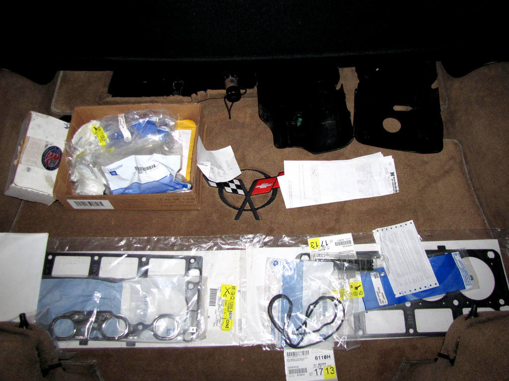
My bolts came with this threadlocking compound already on the bolts. I got all my parts from my local Chevy dealer.
Before you install your cylinder heads, you are going to want to have them checked out. They may be slightly warped, especially if your engine overheated at some point. The cylinder heads may need to be shaved to ensure that they are perfectly flat. DO NOT skip this step. Have your heads inspected and machined if necessary by a quality shop. I paid about $180 to have my inspected and shaved. They removed .0006 (thousandths) of an inch to make them perfect. Not much at all and that did not change any characteristics of my motor.
Important
Do not reuse the cylinder head bolts. Install NEW cylinder head bolts during assembly.
Do not use any type of sealant on the cylinder head gasket (unless specified).
The cylinder head gasket must be installed in the proper direction and position.
Caution
Wear safety glasses in order to avoid eye damage.
Notice
Clean all dirt, debris, and coolant from the engine block cylinder head bolt holes. Failure to remove all foreign material may result in damaged threads, improperly tightened fasteners or damage to components.
Here's a picture from the service manual which shows the cylinder head locating pins and how they are supposed to be inserted into the block (just in case yours are removed or come out).
Step 1. Clean the engine block head bolt holes (if required). Thread repair tool J 42385-107 may be used to clean the threads of the old threadlocking material.
I got myself a spiral wire brush and used brake cleaning fluid to clean out my bolt holes. Then I used my fancy vacuum cleaner with a small tube attachment to suck everything out of the holes. Some people will use their old bolts to clean the holes by running them in and out of the bolt holes. It is imperative that you get EVERYTHING out of those bolt holes before reassembly. Failure to do so could cause another leak to develop. The next steps are the way the service manual has you do it. Make sure you are wearing your safety glasses if you do it this way!
Step 2. Spray cleaner GM U.S. P/N 12346139, P/N 12377981, Canada P/N 10953463, or equivalent into the hole.
Step 3. Clean the cylinder head holes with compressed air
Step 4. Check the cylinder head locating pins for proper installation.
Before performing the next step, make sure that you clean ALL of the old gasket off the engine block. Failure to do so will result in another leak! Here's what mine looked like after I cleaned it. It's the driver's side but you get the drift. I used a soft scrubby pad and some Simple Green. DO NOT spray Simple Green directly on the engine. Spray it on the soft scrubby sponge and use that to clean the surface. If Simple Green is left sitting on aluminum long enough, it can cause pitting and it will eat at your gaskets.
Step 5. Install the NEW cylinder head gasket onto the locating pins.
Pay special attention to the orientation of the new gasket and make sure that you install the correct side facing upward! See the pictures below. These are of the driver's side but the wording on the gaskets are what you need to pay special attention to.
Important
When properly installed, the tab on the right cylinder head gasket will be located left of center, or closer to the front of the engine, and the words "This Side Up", and the engine displacement, will be visible.
Step 6. Inspect the gasket for proper installation.
Step 7. Install the cylinder head onto the locating pins and the gasket.
Be careful not to drop the heads and gouge anything!
Step 8. Install NEW cylinder head bolts.
Hand tighten them into their respective holes. Here's the layout again if you have forgotten.
Step 9. Tighten the cylinder head bolts.
Okay, here comes the fun part!!!
If you have never used an angle torque gauge, WATCH THIS VIDEO! It not only explains how to use the thing, it also explains why you are tightening the bolts to the degree that you are, and why you cannot reuse your old bolts. I found this video to be invaluable given the amount of information contained within it. Also, the guy in the video explains everything so well that even I understood it. Remember, I'm the guy who didn't even know what a head gasket was when I started this repair!
Notice
Use the correct fastener in the correct location. Replacement fasteners must be the correct part number for that application. Fasteners requiring replacement or fasteners requiring the use of thread locking compound or sealant are identified in the service procedure. Do not use paints, lubricants, or corrosion inhibitors on fasteners or fastener joint surfaces unless specified. These coatings affect fastener torque and joint clamping force and may damage the fastener. Use the correct tightening sequence and specifications when installing fasteners in order to avoid damage to parts and systems.
Here is your torque sequence:
Here are your torque values:
- Tighten the M11 cylinder head bolts (1-10) a first pass in sequence to 30 N�m (22 lb ft).
- Tighten the M11 cylinder head bolts a second pass in sequence to 90 degrees using the J 36660-A .
- Tighten the M11 cylinder head bolts (1,2,3,4,5,6,7,8) to 90 degrees and the M11 cylinder head bolts (9 and 10) to 50 degrees a final pass in sequence using J 36660-A .
- Tighten the M8 cylinder head bolts (11-15) to 30 N�m (22 lb ft). Begin with the center bolt (11) and alternating side-to-side, work outward tightening all of the bolts.
Step 10. Install the wiring harness to the clip at the rear of the cylinder head.
Step 11. Position the oil level indicator tube into place.
Step 12. Install the oil level indicator tube bolt. Tighten the oil level indicator tube bolt to 25 N�m (18 lb ft).
Install the Exhaust Manifold
Important
Tighten the exhaust manifold bolts as specified in the service procedure. Improperly installed and/or leaking exhaust manifold gaskets may effect vehicle emissions and/or On-Board Diagnostics (OBD) II system performance.
The cylinder head exhaust manifold bolt hole threads must be clean and free of debris or threadlocking material.
Notice
Use the correct fastener in the correct location. Replacement fasteners must be the correct part number for that application. Fasteners requiring replacement or fasteners requiring the use of thread locking compound or sealant are identified in the service procedure. Do not use paints, lubricants, or corrosion inhibitors on fasteners or fastener joint surfaces unless specified. These coatings affect fastener torque and joint clamping force and may damage the fastener. Use the correct tightening sequence and specifications when installing fasteners in order to avoid damage to parts and systems.
Step 1. If necessary, install the exhaust manifold heat shield and bolts. Tighten the exhaust manifold heat shield bolts to 9 N�m (80 lb in).
Step 2. Apply a 5 mm (0.2 in) wide band of threadlock GM P/N 12345493 or equivalent to the threads of the exhaust manifold bolts.
My bolts came with this threadlocking compound already on the bolts. I got all my parts from my local Chevy dealer.
Last edited by Junkman2008; 09-14-2012 at 05:46 AM.
09-13-2012, 11:08 AM
#5
TECH Apprentice
Thread Starter
(con't)
Step 3. Position the exhaust manifold and a NEW gasket into place.
Step 4. Install the exhaust manifold bolts.
Step 5. Bend over the exposed edge of the exhaust manifold gasket at the front of the right cylinder head.
Valve Rocker Arm and Push Rod Replacement
Important
When reusing the valvetrain components, always install the components to the original location and position.
Valve lash is net build, no valve adjustment is required.
In other words, there is no need to locate top dead center (TDC). Just drop the rods and rockers in place and tighten to spec.
Step 1. Lubricate the valve rocker arms and pushrods with clean engine oil.
Step 2. Lubricate the flange of the valve rocker arm bolts with clean engine oil. Lubricate the flange or washer surface of the bolt that will contact the valve rocker arm.
Step 3. Install the valve rocker arm pivot support.
Important!!!
Make sure that the pushrods seat properly to the valve lifter sockets.
Step 4. Install the pushrods.
Important
Make sure that the pushrods seat properly to the ends of the rocker arms.
Step 5. Install the rocker arms and bolts. DO NOT tighten the rocker arm bolts at this time.
I am going to include this next instruction because it is in the service manual, although it completely conflicts with an earlier instruction. Remember at the beginning of this section how it clearly states that the valve lash is NOT adjustable? If that is the case (and I can 100% verify that the valve lash is NOT adjustable), then step 6 is completely unnecessary. The only reason that I am going to include it is for those individuals who may be working on a engine where the valve lash IS adjustable. For everyone else, ignore step 6 and go to step 7.
Step 6. Rotate the crankshaft until the number one piston is at top dead center (TDC) of the compression stroke. In this position, cylinder number one rocker arms will be off lobe lift, and the crankshaft sprocket key will be at the 1:30 position. The engine firing order is 1,8,7,2,6,5,4,3. Cylinders 1,3,5, and 7 are left bank. Cylinders 2,4,6, and 8 are right bank.
Notice
Use the correct fastener in the correct location. Replacement fasteners must be the correct part number for that application. Fasteners requiring replacement or fasteners requiring the use of thread locking compound or sealant are identified in the service procedure. Do not use paints, lubricants, or corrosion inhibitors on fasteners or fastener joint surfaces unless specified. These coatings affect fastener torque and joint clamping force and may damage the fastener. Use the correct tightening sequence and specifications when installing fasteners in order to avoid damage to parts and systems.
Step 7. With the engine in the number one firing position, tighten the following valve rocker arm bolts:
Again, do not worry about locating TDC. Just tighten the bolts to the correct torque value.
Step 8. Rotate the crankshaft 360 degrees.
If your valve lash is not adjustable, ignore this step.
Step 9. Tighten the following valve rocker arm bolts.
Step 10. Install the valve rocker arm covers.
Valve Rocker Arm Cover Replacement - Right
Important
Step 1. If necessary, lubricate the O-ring seal of the NEW oil fill tube with clean engine oil.
Step 2. If necessary, insert the NEW oil fill tube into the rocker arm cover. Rotate the tube clockwise until locked in the proper position.
Step 3. If necessary, install the oil fill cap into the tube. Rotate the cap clockwise until locked in the proper position.
Step 4. Install a NEW gasket (1) into the valve rocker cover lip.
Step 5. Install the valve rocker arm cover onto the cylinder head.
Notice
Use the correct fastener in the correct location. Replacement fasteners must be the correct part number for that application. Fasteners requiring replacement or fasteners requiring the use of thread locking compound or sealant are identified in the service procedure. Do not use paints, lubricants, or corrosion inhibitors on fasteners or fastener joint surfaces unless specified. These coatings affect fastener torque and joint clamping force and may damage the fastener. Use the correct tightening sequence and specifications when installing fasteners in order to avoid damage to parts and systems.
Step 6. Tighten the rocker arm cover bolts.
Tighten the valve rocker arm cover bolts to 12 N�m (106 lb in).
Step 7. Install the ignition coil bracket.
Step 8. Apply threadlock GM P/N 12345382, Canada P/N 10953489, or equivalent to the threads of the bracket studs.
Step 9. Install the ignition coil bracket studs.
Tighten the ignition coil bracket studs to 12 N�m (106 lb in).
Step 10. Connect the ignition coil wire harness main electrical connector.
Step 11. Install the spark plug wires to the ignition coils.
Install the Spark Plugs
Step 1. Inspect each spark plug gap. Adjust each plug as needed.
Specification:
Spark plug gap: 1 524 mm (0.060 in)
Step 2. Hand start the spark plugs in the corresponding cylinders.
Notice
Use the correct fastener in the correct location. Replacement fasteners must be the correct part number for that application. Fasteners requiring replacement or fasteners requiring the use of thread locking compound or sealant are identified in the service procedure. Do not use paints, lubricants, or corrosion inhibitors on fasteners or fastener joint surfaces unless specified. These coatings affect fastener torque and joint clamping force and may damage the fastener. Use the correct tightening sequence and specifications when installing fasteners in order to avoid damage to parts and systems.
Step 3. Tighten the spark plugs.
Step 4. Install the spark plug wires.
Other Torque Values
HO2 Sensor
Tighten the HO2S to 41 N�m (30 lb ft).
Exhaust Manifold Nuts
Tighten the exhaust manifold nuts to 20 N�m (15 lb ft).
AIR Pipe Bolts
Tighten the AIR pipe bolts to 20 N�m (15 lb ft).
That covers all of your torque values for the right side of the engine. The left side is a totally different animal. I don't know how long that is going to take me to writeup but I should get it done sometime before the new year!
Step 3. Position the exhaust manifold and a NEW gasket into place.
Step 4. Install the exhaust manifold bolts.
- Tighten the exhaust manifold bolts a first pass to 15 N•m (11 lb ft). Tighten the exhaust manifold bolts beginning with the center two bolts. Alternate from side-to-side, working toward the outside bolts.
- Tighten the exhaust manifold bolts a final pass to 25 N•m (18 lb ft). Tighten the exhaust manifold bolts beginning with the center two bolts. Alternate from side-to-side, working toward the outside bolts.
Step 5. Bend over the exposed edge of the exhaust manifold gasket at the front of the right cylinder head.
Valve Rocker Arm and Push Rod Replacement
Important
When reusing the valvetrain components, always install the components to the original location and position.
Valve lash is net build, no valve adjustment is required.
In other words, there is no need to locate top dead center (TDC). Just drop the rods and rockers in place and tighten to spec.
Step 1. Lubricate the valve rocker arms and pushrods with clean engine oil.
Step 2. Lubricate the flange of the valve rocker arm bolts with clean engine oil. Lubricate the flange or washer surface of the bolt that will contact the valve rocker arm.
Step 3. Install the valve rocker arm pivot support.
Important!!!
Make sure that the pushrods seat properly to the valve lifter sockets.
Step 4. Install the pushrods.
Important
Make sure that the pushrods seat properly to the ends of the rocker arms.
Step 5. Install the rocker arms and bolts. DO NOT tighten the rocker arm bolts at this time.
I am going to include this next instruction because it is in the service manual, although it completely conflicts with an earlier instruction. Remember at the beginning of this section how it clearly states that the valve lash is NOT adjustable? If that is the case (and I can 100% verify that the valve lash is NOT adjustable), then step 6 is completely unnecessary. The only reason that I am going to include it is for those individuals who may be working on a engine where the valve lash IS adjustable. For everyone else, ignore step 6 and go to step 7.
Step 6. Rotate the crankshaft until the number one piston is at top dead center (TDC) of the compression stroke. In this position, cylinder number one rocker arms will be off lobe lift, and the crankshaft sprocket key will be at the 1:30 position. The engine firing order is 1,8,7,2,6,5,4,3. Cylinders 1,3,5, and 7 are left bank. Cylinders 2,4,6, and 8 are right bank.
Notice
Use the correct fastener in the correct location. Replacement fasteners must be the correct part number for that application. Fasteners requiring replacement or fasteners requiring the use of thread locking compound or sealant are identified in the service procedure. Do not use paints, lubricants, or corrosion inhibitors on fasteners or fastener joint surfaces unless specified. These coatings affect fastener torque and joint clamping force and may damage the fastener. Use the correct tightening sequence and specifications when installing fasteners in order to avoid damage to parts and systems.
Step 7. With the engine in the number one firing position, tighten the following valve rocker arm bolts:
- Tighten the exhaust valve rocker arm bolts 1,2,7, and 8 to 30 N�m (22 lb ft).
- Tighten the intake valve rocker arm bolts 1,3,4, and 5 to 30 N�m (22 lb ft).
Again, do not worry about locating TDC. Just tighten the bolts to the correct torque value.
Step 8. Rotate the crankshaft 360 degrees.
If your valve lash is not adjustable, ignore this step.
Step 9. Tighten the following valve rocker arm bolts.
- Tighten the exhaust valve rocker arm bolts 3,4,5, and 6 to 30 N�m (22 lb ft).
- Tighten the intake valve rocker arm bolts 2,6,7, and 8 to 30 N�m (22 lb ft).
Step 10. Install the valve rocker arm covers.
Valve Rocker Arm Cover Replacement - Right
Important
- All gasket surfaces should be free of oil and other foreign material during assembly.
- DO NOT reuse the valve rocker arm cover gasket.
- The valve rocker arm cover bolt grommets may be reused.
- If the oil fill tube has been removed from the rocker arm cover, install a NEW fill tube during assembly.
Step 1. If necessary, lubricate the O-ring seal of the NEW oil fill tube with clean engine oil.
Step 2. If necessary, insert the NEW oil fill tube into the rocker arm cover. Rotate the tube clockwise until locked in the proper position.
Step 3. If necessary, install the oil fill cap into the tube. Rotate the cap clockwise until locked in the proper position.
Step 4. Install a NEW gasket (1) into the valve rocker cover lip.
Step 5. Install the valve rocker arm cover onto the cylinder head.
Notice
Use the correct fastener in the correct location. Replacement fasteners must be the correct part number for that application. Fasteners requiring replacement or fasteners requiring the use of thread locking compound or sealant are identified in the service procedure. Do not use paints, lubricants, or corrosion inhibitors on fasteners or fastener joint surfaces unless specified. These coatings affect fastener torque and joint clamping force and may damage the fastener. Use the correct tightening sequence and specifications when installing fasteners in order to avoid damage to parts and systems.
Step 6. Tighten the rocker arm cover bolts.
Tighten the valve rocker arm cover bolts to 12 N�m (106 lb in).
Step 7. Install the ignition coil bracket.
Step 8. Apply threadlock GM P/N 12345382, Canada P/N 10953489, or equivalent to the threads of the bracket studs.
Step 9. Install the ignition coil bracket studs.
Tighten the ignition coil bracket studs to 12 N�m (106 lb in).
Step 10. Connect the ignition coil wire harness main electrical connector.
Step 11. Install the spark plug wires to the ignition coils.
Install the Spark Plugs
Step 1. Inspect each spark plug gap. Adjust each plug as needed.
Specification:
Spark plug gap: 1 524 mm (0.060 in)
Step 2. Hand start the spark plugs in the corresponding cylinders.
Notice
Use the correct fastener in the correct location. Replacement fasteners must be the correct part number for that application. Fasteners requiring replacement or fasteners requiring the use of thread locking compound or sealant are identified in the service procedure. Do not use paints, lubricants, or corrosion inhibitors on fasteners or fastener joint surfaces unless specified. These coatings affect fastener torque and joint clamping force and may damage the fastener. Use the correct tightening sequence and specifications when installing fasteners in order to avoid damage to parts and systems.
Step 3. Tighten the spark plugs.
- For cylinder head-new: Tighten the spark plugs to 20 N�m (15 lb ft).
- For cylinder head-all subsequent installations: Tighten the spark plugs to 15 N�m (11 lb ft).
Step 4. Install the spark plug wires.
Other Torque Values
HO2 Sensor
Tighten the HO2S to 41 N�m (30 lb ft).
Exhaust Manifold Nuts
Tighten the exhaust manifold nuts to 20 N�m (15 lb ft).
AIR Pipe Bolts
Tighten the AIR pipe bolts to 20 N�m (15 lb ft).
That covers all of your torque values for the right side of the engine. The left side is a totally different animal. I don't know how long that is going to take me to writeup but I should get it done sometime before the new year!
Last edited by Junkman2008; 09-13-2012 at 11:18 AM.

Trending Topics
09-13-2012, 01:02 PM
#8
TECH Enthusiast
iTrader: (7)

Join Date: Jun 2010
Location: IL
Posts: 635
Likes: 0
Received 0 Likes
on
0 Posts
Wow. Very detailed, informative and thorough write up. This is one of the best how-to write ups I've ever seen. This must have taken just as much time as the actual job itself. I applaud your effort! 
09-13-2012, 01:18 PM
#9
TECH Apprentice
Thread Starter
The only reason that I work on my car is because I've seen what the dealership hacks do and I swear, I think some of them know less about cars than I do. I have the same service manual that the GM dealerships have and they couldn't figure out half the problems that I use to bring them the car for. After finding car forums on the Internet, I never went back to a dealer. That was 2008, and the only tools I had were a pipe wrench and a Phillips screw driver.
Now I'm a tool buyin', wrench turnin', writeup producin' fool!


 09-14-2012, 12:25 AM
#14
TECH Apprentice
Thread Starter
 09-14-2012, 05:40 AM
#16
TECH Apprentice
Thread Starter
 09-14-2012, 07:59 PM
#18
TECH Apprentice
Thread Starter
