


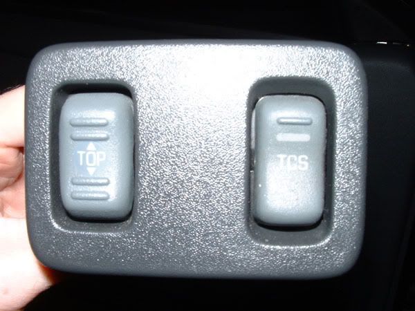


Using convertible switch to power QTP electic cutout
Thread Starter
TECH Fanatic
iTrader: (9)
Joined: Feb 2002
Posts: 1,061
Likes: 0
From: West Lafayette, IN
I was searching for some new ideas on how to mount my electric cutout switch and saw mention of using a convertible switch to operate the cutout. Unfortunately, I couldn't find any instructions on how to actually wire the switch to the cutout. Does anyone have any instructions (or better still, a schematic) that explain how to do this?
Thanks,
Josh
Thanks,
Josh
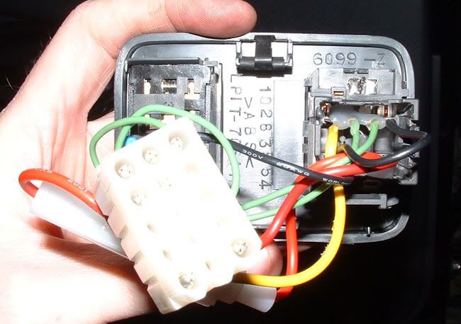
Pretend that you already have a convertible top harness installed in the car, and the plug is just sitting there without the switch connected. Take the connector and orient it so that the locking tab is on top, and the plug is facing you. With this pictured in your mind, this is the connections of that plug:
TAB
H G F E
A B C D
H = Ground
G = Empty (not used)
F = Power (12v)
E = Up (+) Cutout (open)
A = Down (-) Cutout (close)
B = Lamp (+)
C = Lamp (-)
D = Ground
There are two grounds. In order for the switch to reverse the polarities for the up/down (+/-) to open and close the cutout, connector "H" and "D" have to be jumped together to the ground on the vehicle.
Holding the actual switch in your hand, it will be upside down so the locking tab part will be oriented on top. This should help you figure out what pin is what on the switch, use pin "G" as a guide.
Since I soldered the wires directly to the tabs on the back of the switch, you have to flip the diagram over, like this.
TAB
E F G H
D C B A
H = Ground
G = Empty (not used)
F = Power (12v)
E = Up (+) Cutout (open)
A = Down (-) Cutout (close)
B = Lamp (+)
C = Lamp (-)
D = Ground
B and C are interchangable for the light, so they don't matter. This switch is a basic reverse polarity unit. When you press one direction, A becomes + and E becomes -. Press the other way and A becomes - and E becomes +. Get it?
TAB
H G F E
A B C D
H = Ground
G = Empty (not used)
F = Power (12v)
E = Up (+) Cutout (open)
A = Down (-) Cutout (close)
B = Lamp (+)
C = Lamp (-)
D = Ground
There are two grounds. In order for the switch to reverse the polarities for the up/down (+/-) to open and close the cutout, connector "H" and "D" have to be jumped together to the ground on the vehicle.
Holding the actual switch in your hand, it will be upside down so the locking tab part will be oriented on top. This should help you figure out what pin is what on the switch, use pin "G" as a guide.
Since I soldered the wires directly to the tabs on the back of the switch, you have to flip the diagram over, like this.
TAB
E F G H
D C B A
H = Ground
G = Empty (not used)
F = Power (12v)
E = Up (+) Cutout (open)
A = Down (-) Cutout (close)
B = Lamp (+)
C = Lamp (-)
D = Ground
B and C are interchangable for the light, so they don't matter. This switch is a basic reverse polarity unit. When you press one direction, A becomes + and E becomes -. Press the other way and A becomes - and E becomes +. Get it?
Man this is old, but I think I remember.
The lamp circuit is it's own thing to power the light bulb built into the switch. I tapped mine + to + and - to - to the lamp wires for the TCS.
Now if you don't have TCS you can tap them into the cutouts power wires since they are ignition controlled. The lamp will turn on with the key, but it shouldn't be a problem.
Now if your **** and don't want the button to light up in the daytime then you'll need to run the lamp wires to a circuit tied into the light switch like the dash lights for example.
Trending Topics
LS1 Tech Stories
The Best V8 Stories One Small Block at Time

6 Gifts Neither Your Dad Nor Grad Will Shove Into the 'Trinket Drawer'
Brett Foote
Topdon ONE vs. Artidiag 800 BT2: Which is the Diagnostic Tablet For You?
Pouria Savadkouei
Gas Monkey Built a 6-Wheel Ferrari Testarossa With a Corvette LT4 Engine
Verdad Gallardo
7 Most Reliable High-Performance Engines GM Has Ever Built
Verdad Gallardo
Amazing '71 Camaro Restomod Is Modern Muscle Car Under the Skin
Verdad Gallardo
6 Common C5 Corvette Failures and What's Involved In Repairing Them
Pouria Savadkouei
Retro Modern Bandit Pontiac Trans AM Comes With Burt Reynolds' Autograph
Verdad Gallardo
Top 10 Greatest Cadillac V Series Performance Models Ever, Ranked
Pouria Savadkouei