


LS6 Intake - getting closer
Thread Starter
TECH Enthusiast
iTrader: (2)
Joined: Dec 2007
Posts: 677
Likes: 0
From: Sherwood Park, AB
I picked up a LS6 intake from another member a couple of days ago, and started trying to fit it over the LS4 valley cover.
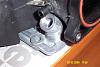
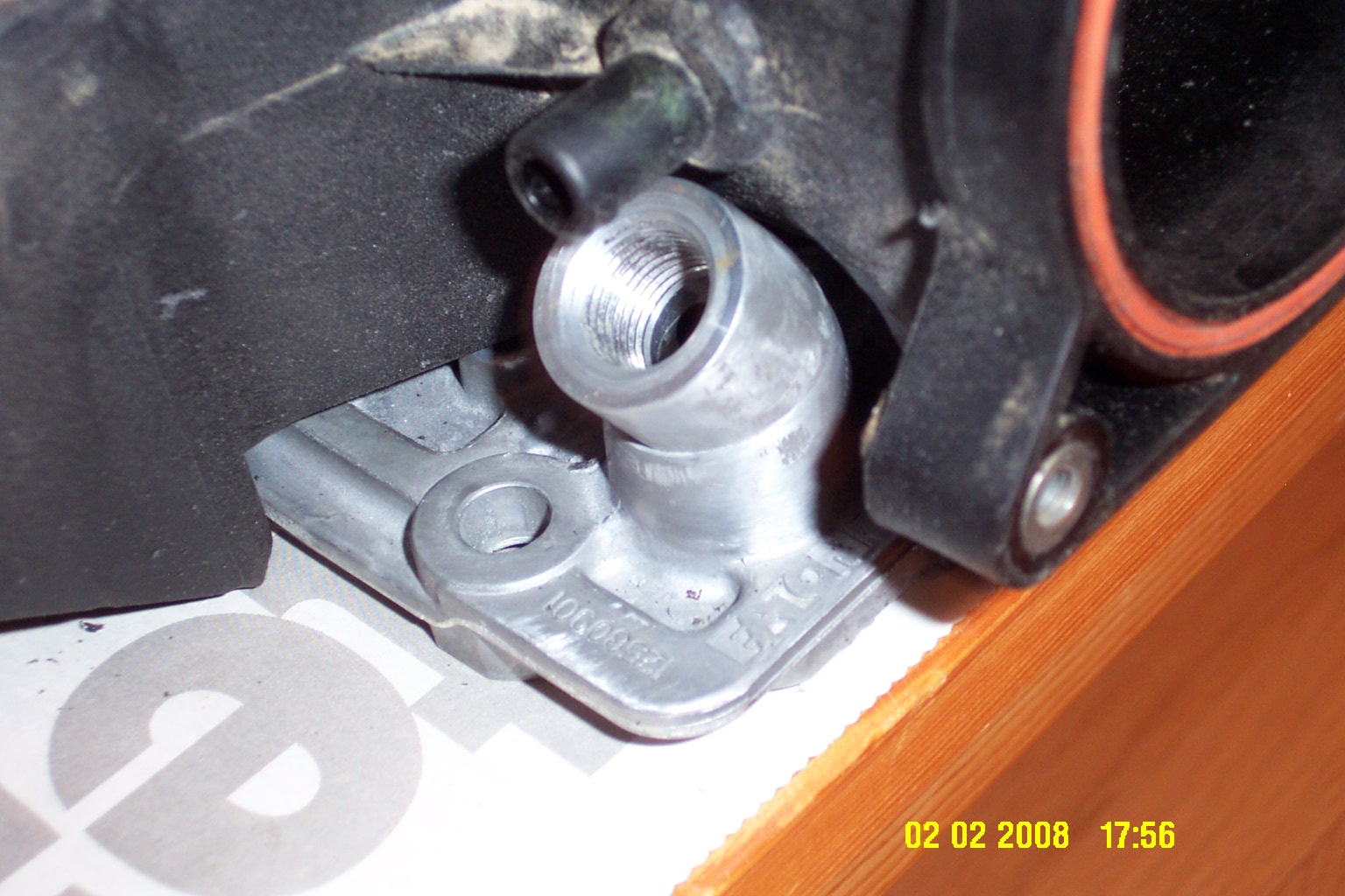
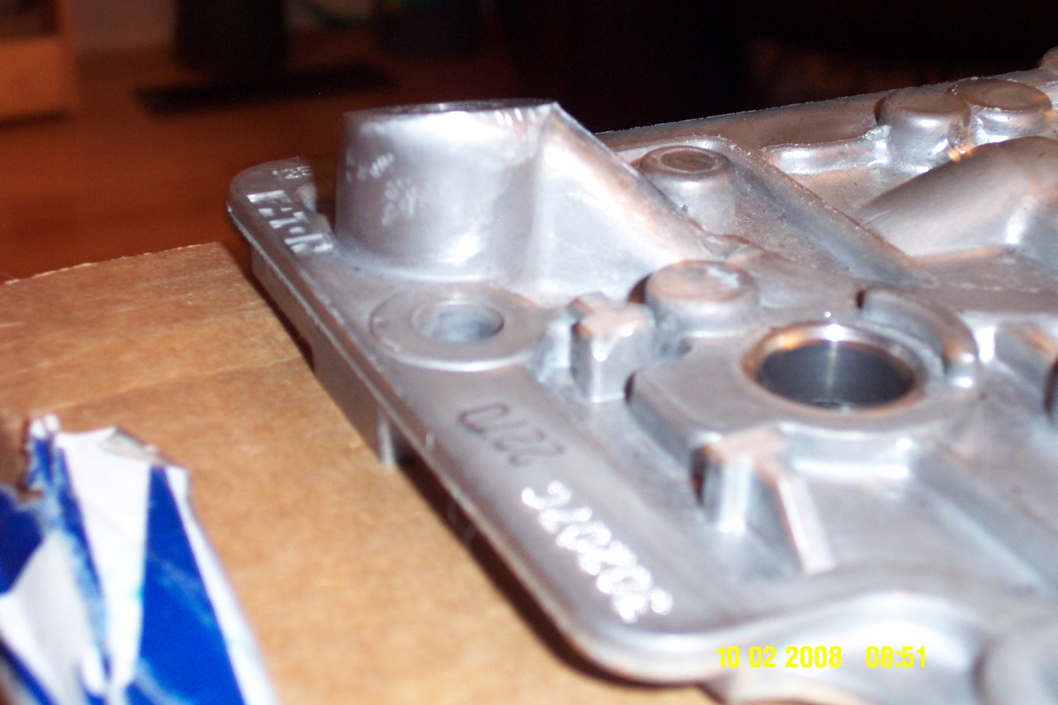
The good news is that, once a vacuum fitting is closed off, I'll have clearance for the oil pressure sending unit. Here's some pics.
Just a couple of mm clearance, but enough.
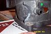
Modification required to the intake's neck to provide clearance
Modification of the DOD connector is in progress, but it is too ugly at the moment to post pictures. Looks like I need to cannibalize two of those connectors to remotely mount the plug, but things look promising.
I'm pretty busy these days, so I don't expect to make any significant progress for the next couple of weeks, just thought I'd share progress to date.

The good news is that, once a vacuum fitting is closed off, I'll have clearance for the oil pressure sending unit. Here's some pics.
Just a couple of mm clearance, but enough.
Modification required to the intake's neck to provide clearance

Modification of the DOD connector is in progress, but it is too ugly at the moment to post pictures. Looks like I need to cannibalize two of those connectors to remotely mount the plug, but things look promising.
I'm pretty busy these days, so I don't expect to make any significant progress for the next couple of weeks, just thought I'd share progress to date.
I picked up a LS6 intake from another member a couple of days ago, and started trying to fit it over the LS4 valley cover.
The good news is that, once a vacuum fitting is closed off, I'll have clearance for the oil pressure sending unit. Here's some pics.
Just a couple of mm clearance, but enough.
Attachment 118590
Modification required to the intake's neck to provide clearance
Attachment 118591
Modification of the DOD connector is in progress, but it is too ugly at the moment to post pictures. Looks like I need to cannibalize two of those connectors to remotely mount the plug, but things look promising.
I'm pretty busy these days, so I don't expect to make any significant progress for the next couple of weeks, just thought I'd share progress to date.

Looking good! You'v beat me to the punch on this mod. Couldn't you just plan on angling the oil pressure switch outlet to the front slightly before welding it in place to clear the vacuum outlet on the intake rather than closing the vaccum port and have the best of both?
Thread Starter
TECH Enthusiast
iTrader: (2)
Joined: Dec 2007
Posts: 677
Likes: 0
From: Sherwood Park, AB
John B
The picture doesn't really give the right perspective on how close the vacuum fitting is to the top of the oil pressure sending unit mount. Not enough clearance is available through rotating the mount. Based on how I angled the original cut, closing the fitting off seems to be the only option.
It may be possible to do as you have suggested if the mount was cut differently.
There are three other vacuum fittings in the intake, so I don't think there will be any problems hooking up vacuum lines.
Oh, the MAP sensor mount is relocated to the back end of the manifold instead of the intake neck as on the LS4. I hear that location provides for a more reliable map reading as there is a bit of a pressure gradient near the TB.
Forgot to mention in the OP that there are a number of ribs cast into the bottom of the LS6 manifold (about 5mm high) that need to be clearanced for the manifold to sit down over the valley cover. Some alignment "lugs" surrounding the DOD connector also needed to be ground down several mm so that they do not stick up past the other bumps cast into the valley cover.
I also need to start designing the adapter plate to fit the 4 bolt TB to the three bolt manifold flange. I measured the TB and intake opening, both came in at 76mm (just about bang on 3"), so no fancy smoothing will be required on the adapter plate. I suppose I should do a search to see if there is one commercially available, could save a few headaches.
Thread Starter
TECH Enthusiast
iTrader: (2)
Joined: Dec 2007
Posts: 677
Likes: 0
From: Sherwood Park, AB
One off, if I have to build it myself. I'd really rather find one commercially, since my metal working tools are limited (saws, drill press, grinders, dremel, wire feed welder). Then again, aluminum is pretty easy to work, so an adaper could be made with these basic tools.
I'd at least make the full scale template available, unless someone else beats me to it.
I'd at least make the full scale template available, unless someone else beats me to it.
Trending Topics
Thread Starter
TECH Enthusiast
iTrader: (2)
Joined: Dec 2007
Posts: 677
Likes: 0
From: Sherwood Park, AB
Well, I struck out in my search for an adapter to mount the 4 bolt throttle body to the three bolt pattern on the LS6 intake 
The closest I could come up with is an outfit called TPIS that modifies LS6 intakes to mount a 90mm LS2 four bolt throttle body, but that won't clear the oil pressure sending unit, so it's out.
Anybody else come across an adapter plate on the web? If not, I guess I get to design and build one.
The closest I could come up with is an outfit called TPIS that modifies LS6 intakes to mount a 90mm LS2 four bolt throttle body, but that won't clear the oil pressure sending unit, so it's out.
Anybody else come across an adapter plate on the web? If not, I guess I get to design and build one.
LS1 Tech Stories
The Best V8 Stories One Small Block at Time

Topdon ONE vs. Artidiag 800 BT2: Which is the Diagnostic Tablet For You?
Pouria Savadkouei
Gas Monkey Built a 6-Wheel Ferrari Testarossa With a Corvette LT4 Engine
Verdad Gallardo
7 Most Reliable High-Performance Engines GM Has Ever Built
Verdad Gallardo
Amazing '71 Camaro Restomod Is Modern Muscle Car Under the Skin
Verdad Gallardo
6 Common C5 Corvette Failures and What's Involved In Repairing Them
Pouria Savadkouei
Retro Modern Bandit Pontiac Trans AM Comes With Burt Reynolds' Autograph
Verdad Gallardo
Top 10 Greatest Cadillac V Series Performance Models Ever, Ranked
Pouria Savadkouei
Top 10 Most Powerful Chevy Trucks Ever Made!

Hennessey's New Supercharged Silverado ZR2 Has 700 HP
Verdad Gallardo If you don't have a way to do this, maybe donrome over at clubGP could do something for you, given detailed specs? He designed and fabbed the billet alum. brackets for installing STB's in the GP, Imp and Monte.

Staging Lane
Joined: Feb 2007
Posts: 78
Likes: 0
Just a shot in the dark, has anyone seen the intake for a LH6 before? I know the 07+ is a 5.3L and DoD. It has a 87mm throttle body as well. Of course, it's designed for a rwd setup, but given that truck intake necks point upwards at an angle, it might fit better.
I know they are uglier, and look to have a longer runner design, but it might be a viable option. I haven't had any luck finding a picture of one personally.
I know they are uglier, and look to have a longer runner design, but it might be a viable option. I haven't had any luck finding a picture of one personally.
Thread Starter
TECH Enthusiast
iTrader: (2)
Joined: Dec 2007
Posts: 677
Likes: 0
From: Sherwood Park, AB
As BADLS1SS stated, the larger neck won't clear the oil pressure sending unit. The LS6 just clears the modified mount by 2 mm. So much for my initial optimism for a 90.
I actually considered the LS2 for a while, but then figured: no clearance, extra $ for new TB, extra $ for new MAF = not worth it. The clincher was when I came across this dyno comparison of LS6/78mm tb vs, LS2/90mm tb - the LS6/78 produced more torque and generally more power as the LS2/90.
http://www.gearchatter.com/viewtopic11052.php
I have relatively modest power goals: 300 to 310 at the wheels, so no reason to increase TB size.
Thread Starter
TECH Enthusiast
iTrader: (2)
Joined: Dec 2007
Posts: 677
Likes: 0
From: Sherwood Park, AB
Just a shot in the dark, has anyone seen the intake for a LH6 before? I know the 07+ is a 5.3L and DoD. It has a 87mm throttle body as well. Of course, it's designed for a rwd setup, but given that truck intake necks point upwards at an angle, it might fit better.
I know they are uglier, and look to have a longer runner design, but it might be a viable option. I haven't had any luck finding a picture of one personally.
I know they are uglier, and look to have a longer runner design, but it might be a viable option. I haven't had any luck finding a picture of one personally.
edit: longer runners generally mean more low end torque, not sure we really need more grunt at the bottom end.

Okay, I've studied this thing enough now....how about cutting the oil pressure sensor down flush to the top of the valley cover (to eliminate it coming up 90* for 1/2") and welding the new threaded piece at an angle right at the top of the valley cover like my crude drawing below for an extra ~3/8" to 1/2" of clearance?
Thread Starter
TECH Enthusiast
iTrader: (2)
Joined: Dec 2007
Posts: 677
Likes: 0
From: Sherwood Park, AB
Okay, I've studied this thing enough now....how about cutting the oil pressure sensor down flush to the top of the valley cover (to eliminate it coming up 90* for 1/2") and welding the new threaded piece at an angle right at the top of the valley cover like my crude drawing below for an extra ~3/8" to 1/2" of clearance?
Here's another couple of pics that shows how the oil supply to the DOD solenoids is tapped off the oil pressure sending unit mount. I've cut the mount down as far as I can without running into the DOD oil feed. Since I want to retain the DOD functionality, I can't cut it any shorter. I suppose the oil feed to the DOD solenoids could be relocated as well, just not by me
 (fab skills/tools lacking)
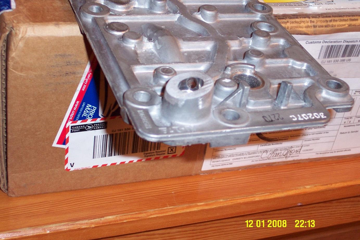
I suppose if someone didn't want to retain DOD, they could just cut the mount off flush and plug it. In which case it would make sense to change valley cover as well to get rid of clearance problems with all the bumps on the LS4 cover. The block could be drilled and tapped to mount the sending unit on the side of the block. I would only consider that If I had the engine pulled and completely disassembled, so I could ensure that any metal shavings were flushed out of the oil galleries.
Hmmm, someone with the right skills probably could retain the oil feed to the DOD solenoids and move the sending unit to the block to fit a 90mm intake.
Last edited by TiredGXP; Feb 10, 2008 at 09:01 AM. Reason: to add another picture
Can you post a pic of the underside of the valley cover where the oil sensor plugs into? My other comments would be to completely weld over the existing passage flush with the top of the valley cover and re-drill the oil passage to where you want it!
Thread Starter
TECH Enthusiast
iTrader: (2)
Joined: Dec 2007
Posts: 677
Likes: 0
From: Sherwood Park, AB
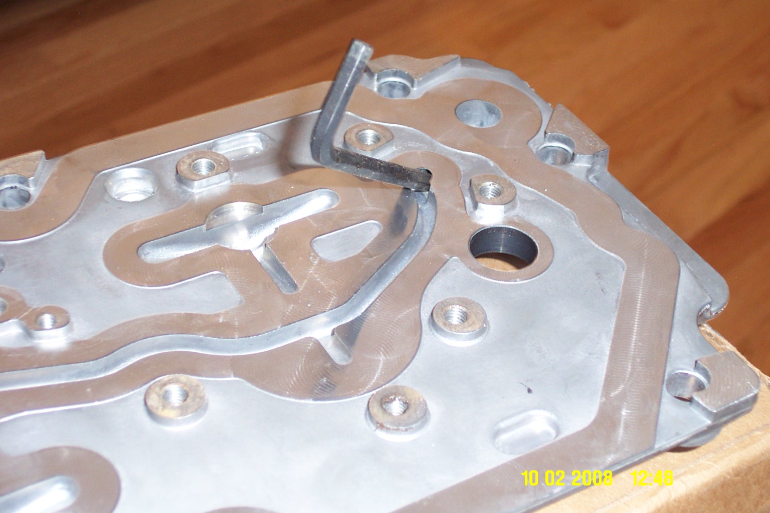
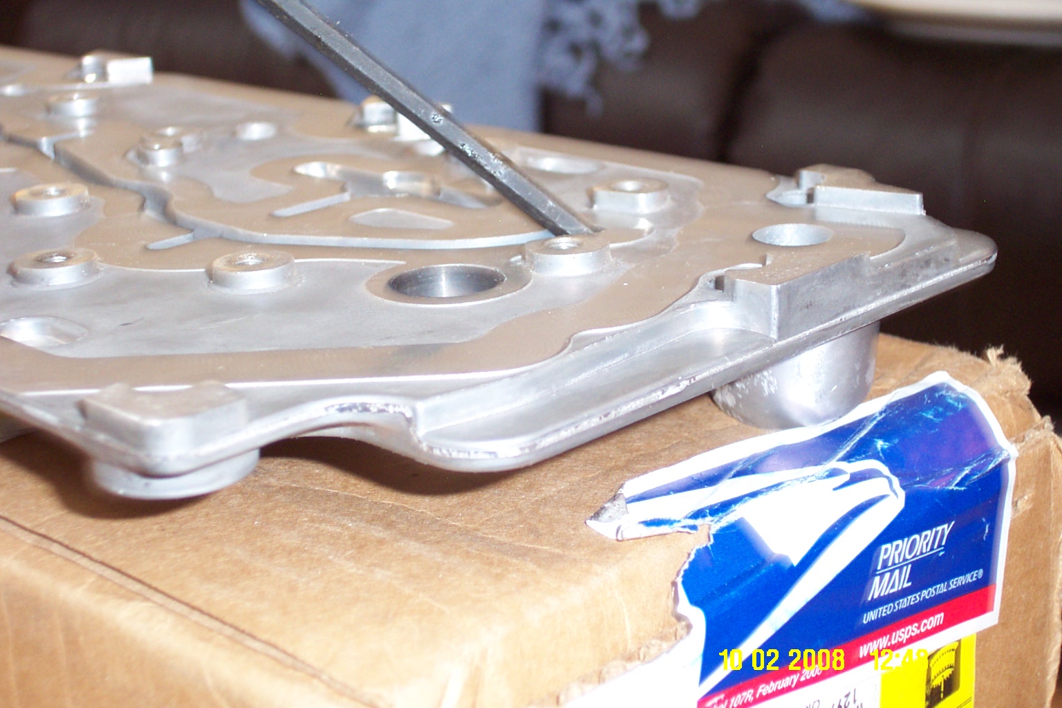

Just for perspective I have an Allen wrench inserted into the DOD oil feed from the oil pressure sending unit. This is a 6mm (.25") channel. Notice that for most of it's length, the oil supply channel is just a groove in the valley cover that is closed off by a gasket for the DOD solenoid mount.