Wiring warning lights for electric waterpump
 04-04-2011, 06:30 PM
#1
Staging Lane
Thread Starter

Join Date: Dec 2007
Posts: 78
Likes: 0
Received 0 Likes
on
0 Posts

Okay after doing some digging and searching around I have found this diagram for wiring up warning lights for pump fuse failure or ground failure.
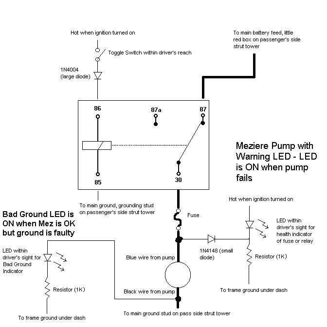
After looking at the diagram, I can see how the led would come on if the ground fails, but I cannot figure out how the led for the fuse failure could come on when the fuse fails.
After reading some more about it, people said that if you just follow the diagram it would work. So over Christmas break I followed the diagram the wired up the two leds. Sure enough, when I removed the ground, the faulty ground led lit up, but when I removed the fuse, the fuse failure led never lit up.
Its possible that I might have mis-wired something or that one of my connections came loose, but even then just by looking at the wiring diagram I have my doubts that this diagram is indeed correct.
Has anybody else used this diagram or one similar and had success?
 04-10-2011, 07:04 PM
#3
Staging Lane
Thread Starter
Join Date: Dec 2007
Posts: 78
Likes: 0
Received 0 Likes
on
0 Posts
Surely somebody has some input on this.
For the ground failing led, here is what I've come up with. When the ground is connected, the current will flow straight to the ground, and bypass the led and resistor since the current wants to take the path of least resistance. When the ground fails, the current is forced to go through the led/resistor node, and thus the led lights up.
Still can't figure out how the fuse failure led works though, so if anybody is good with circuits and wants to explain, chime in!
04-11-2011, 01:24 AM
#5
Surely somebody has some input on this.
For the ground failing led, here is what I've come up with. When the ground is connected, the current will flow straight to the ground, and bypass the led and resistor since the current wants to take the path of least resistance. When the ground fails, the current is forced to go through the led/resistor node, and thus the led lights up.
Still can't figure out how the fuse failure led works though, so if anybody is good with circuits and wants to explain, chime in!
For the ground failing led, here is what I've come up with. When the ground is connected, the current will flow straight to the ground, and bypass the led and resistor since the current wants to take the path of least resistance. When the ground fails, the current is forced to go through the led/resistor node, and thus the led lights up.
Still can't figure out how the fuse failure led works though, so if anybody is good with circuits and wants to explain, chime in!
Al
04-11-2011, 08:34 AM
#6
exactly im not crazy about that design..........any more than a .7V voltage difference between the pump feed wire where you tap in and the feed to the LED will forward bias the diode off the feed line and cause that LED to come on very dim.............but again.....it will work
04-11-2011, 09:03 AM
#7

you can do it this way too.........its easier and all you need to do is get yourself an extra small relay.........just make the connections to the pump wires close to the pump you you keep yourself protected better..........pretty simple
personally id do it with a current sensing circuit thats the best way but no need to start building circuitry and soldering transistors and crap for something simple like this......
Trending Topics
04-11-2011, 09:24 AM
#9
I know this is going to sound crazy, but why not just have an LED that turns on when the CTS reaches a preset temp?
I mean if your car normally runs at 160-180*, and you hit 210, there's a problem somewhere.
You don't have to wait until you hit 250* to start investigating.
You could even have a green LED inline with the pump to let you know that it's running;
not that they're all that hard to hear with the engine off/key on.
That said, my stock WP lasted about 30k miles
My EWP has been on the car for 5 years without issue.
04-11-2011, 09:50 AM
#10
I know this is going to sound crazy, but why not just have an LED that turns on when the CTS reaches a preset temp?
I mean if your car normally runs at 160-180*, and you hit 210, there's a problem somewhere.
You don't have to wait until you hit 250* to start investigating.
You could even have a green LED inline with the pump to let you know that it's running;
not that they're all that hard to hear with the engine off/key on.
That said, my stock WP lasted about 30k miles
My EWP has been on the car for 5 years without issue.
I mean if your car normally runs at 160-180*, and you hit 210, there's a problem somewhere.
You don't have to wait until you hit 250* to start investigating.
You could even have a green LED inline with the pump to let you know that it's running;
not that they're all that hard to hear with the engine off/key on.
That said, my stock WP lasted about 30k miles
My EWP has been on the car for 5 years without issue.
04-11-2011, 09:56 AM
#11
i agree i think a warning light for too high of a collant temperature is a better idea.......if the pump dies its going to be a very short amount of time till the coolant temp spikes.........this is what im doing with mine right now.......i just got the autometer ultra lite gauge with the built in warning light that u can set at whatver temp you want......i'm doing the same thing with oil pressure......im thinking about wiring the oil pressure warning in so that if the motor drops below 10psi it automatically shuts itself off....only problem with that is when im cranking it to start it I'll have to wait till i get more than 10psi of pressure for it to start......
04-11-2011, 09:58 AM
#12
true true.........i was thinking of just killing the ignition 12 volt wire to the MSD box.......that could work if the starter is cranking i break the kill line from the oil press montior to the relay that will kill the msd...........i'd need two relays but it will work..........hmmmmm....
 04-12-2011, 09:41 AM
#17
i could do either.........one way id just tap into the coolant temp signal at the dash the other way would be two wires up to the water pump itself..........the coollant temp way would need to have a small box like 2 sq inch or so for some small circuitry
04-13-2011, 07:57 AM
#20
i checked everything out last night.......so with a pretty much plug and play kit with instructions/pics.......all soldered and shrink wrapped connections and an LED warning light....figure i can do em for $50 a pop.......lemme know what u guys think....
Mike
Mike