When you click on links to various merchants on this site and make a purchase, this can result in this site earning a commission. Affiliate programs and affiliations include, but are not limited to, the eBay Partner Network.
So I got everything hooked up. I ran into some last minute stuff I need help on the intstall. First thing is the slave cylinder will not clear my headers. And I'm pretty sure it's done, it's not one solid piece anymore. I was wondering do I need to replace the whole thing. Or can I save myself some money and just buy the slave without the line? Second all sensors all hooked up except for one in the picture. Can't remember if it broke. The hose for the opti, and temperature sensor gauge.
I know this goes to the opti where else.
It looks bad...
Yeah real bad
Can't find the connector for the temperature sensor gauge. What does it look like?
The sensor I don't where it goes. It looks broke... Lol
It looks like the slave cylinder clears your headers just fine. At least it looks like the same amount of clearance that I have.
This looks like it goes to the temp sensor on the head, but it seems to have some sort of adapter on it. It's a single wire, which is right for that sensor. Remove the adapter and check to see if the plug fits on the temp sensor. The location of the connector seems right too.
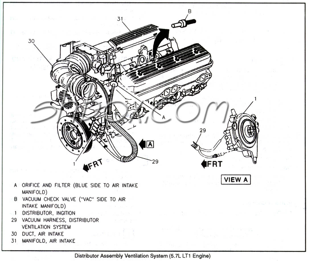
That hose is tee'd. Which is weird. It should be two separate hoses (if it's for the Opti). One would go from the air intake tube (post MAF if you have one, but looking at the PCV on the intake tells me you have a 93) to the back side of the Opti (near the block). The other will run from the intake manifold plenum (vacuum source) to the Cap and Rotor(front side) side of the Opti. You want the air flow to draw away from the optical sensor. So fresh air in through the back (where the optical sensor is) and vacuum pulling it through the cap.
What do you mean 2 pieces? The slave cylinder rod is removable. It just slides in and out of the boot and sits in a cup in the slave cylinder. If you remove the boot you'll see what I'm talking about.
You can replace just the slave cylinder though. There's a roll pin that holds the hydraulic line in to the back of the slave, push it out and the hose pulls right out. Try not to lose the roll pin when you push it out, LOL. Reverse to install the new slave cylinder. To bleed the system you just pump the slave by hand about 20 times making sure the clutch hose is at the highest point of the slave while pumping. Make sure the reservoir is full before and while you are pumping though, also make sure the clutch pedal is all the way up (I wedge something behind the clutch pedal to keep it all the way up).
Well, that's bent. At least it looks bent. Can't say I've ever seen one bent in person before, on any car. You cannot order these separately, they do come with a new slave cylinder though.
See my comment under the first pic. The connector looks very much like the connector for the coolant sensor on the Water Pump, but it only has 1 wire (instead of 2 like the water pump sensor).
The sensor I don't where it goes. It looks broke... Lol
It looks like the slave cylinder clears your headers just fine. At least it looks like the same amount of clearance that I have
To bleed the system you just pump the slave by hand about 20 times making sure the clutch hose is at the highest point of the slave while pumping. Make sure the reservoir is full before and while you are pumping though, also make sure the clutch pedal is all the way up (I wedge something behind the clutch pedal to keep it all the way up.
The slave won't make it all the way to it resting place, either way I slice it it seems like it won't reach. But if I replace the slave can I just bolt it up and connect the hose after?
And when you say pump the slave are you talking about pushing it in?
The slave won't make it all the way to it resting place, either way I slice it it seems like it won't reach. But if I replace the slave can I just bolt it up and connect the hose after?
And when you say pump the slave are you talking about pushing it in?
What do you mean the slave won't go all the way on? It's a little difficult to get it over the studs with the line attached, but it will go on. Then you have to press the rod end as you install it (if the rod end is in the fork correctly, tightening the nuts will draw it in). The slave cylinder is spring loaded and should be full of fluid before you install it. It will fully extend when it's not installed (without the shipping straps in place, with them it's about half way extended). When you install it you have to push against the spring and the hydraulic fluid to get it to seat all the way.
The only way it won't go all the way on is if the rod isn't in the fork cup, the fork is jammed up, the master cylinder is pressed down, or the slave spacer isn't installed.
You have to have that line installed before you put the slave on because you have to bleed the slave if you disconnect the line. The only way to properly bleed The slave is as I noted in my previous post.
Yes, you need to push the slave rod in a bunch of times to push all the air out of the slave cylinder. Usually 10-20 slow strokes will do. Personally this is probably the easiest slave/master clutch cylinders I've ever had to bleed. And even though I've modded my clutch hydraulics and actually have a bleeder screw, I still use this method.
do you have the spacer that first slides on the two studs on the bell housing then you put slave on. Its about 2" thick +/-
looks like you are trying to bolt it direct to bell housing...and managed to bend the slave rod in the process.
since you have to buy a new slave now....put in in a vice with rod pointed down. Unhook the straps so it can come out. Now fill the slave with brake fluid and "gently" using 1/4 strokes pump it a few times so all air gets out of it. Top it off again with brake fluid. Now take the braided line from MC and connect to slave using roll pin. You really want to not lose any fluid making this connection but you will. now with the slave attached let it hang and go top off the reservoir with fluid. from under car pump 1/2 strokes while a friend looks up top for when bubbles stop and he keeps toping off fluid. push slave rod up now so you can put the plastic straps back in their slots. now the slave will EASILY bolt to the bellhousing with spacer. On first time you push clutch pedal the straps will break (normal)
I can't tell by pic but it looks like there is room between slave & header. If really close you will want to wrap slave with heat wrap or you will cook your hydraulics
Ok so basically install the new clutch cylinder to the line, and pump it while someone is watching the the reserivor from the top and refill it when needed and once the bubbles stop install clutch cylinder to the transmission bell housing? Will it leak once I remove it from the line?
you really want to "bench bleed" the new slave first...like I noted earlier, vs just attaching it empty to the steel braided line as it will take forever to get it to fill otherwise if at all
yes you will lose some fluid from the MC and slave in making the attachment. that is why you then need to bleed the whole system by pumping the slave piston as someone else from up top keeps an eye on the reservoir. bleeding these closed systems can be a PIA but doable
otherwise just buy a new complete sealed MC/slave and put that on
did you have the spacer that goes between slave & bellhousing?
I disagree, I think bleeding these closed systems are far easier. And they make it a one man job. If you do it correctly, you'll get all the air out of the system in about 20 pumps. I don't bench bleed, nor do I half pump. I pump the entire slave cylinder from full extension to full compression, by hand, steady and slow about 20 times, making sure the clutch line is at the highest point of the the slave cylinder while pumping. It's really not difficult at all.
OP, once you bleed the system, do NOT open the lines again. You'll have to bleed the system again if you do. Bleeding the system is the last thing you do before installing the slave cylinder to the bellhousing.
That slave cylinder spacer is very important It must be there.
Yeah the spacer on there in the picture. So this is really easy then, last thing not related since both of you gave me good advice. How do you wire this damn EWP, at this point I just need it to work so I can get my car to the port to ship? This is the last two things then I can start her up?
The EWP should've come with a schematic. I've never run one, but if I were to install one, I'd do a dual relay install.
Run the ground of the EWP to a good ground.
Run the power through a relay.
I'd run the first relay (that powers the motor) like so:
-Pin 85 to ground.
-Pin 86 to Ignition power, so when the key is on so is the EWP.
-Pin 30 through the EWP fuse then straight to the Battery +
-Pin 87 to the EWP.
Note: The pin numbers I gave are the pin identifications marked directly on the relay.
The second relay is for monitoring the system for power, it is completely optional. If you don't want to run it, just ignore everything after this point.
-Pin 85 to ground.
-Pin 86 to the ground side of the EWP (this picks up 12V after the EWP if the EWP has power going completely through it, as it should if running), it must be connected to this wire between ground and the EWP.
-Pin 30 to pin 86 of the first relay.
-pin 87a to a lamp (of your choosing, LED 12V should work well) on the dash, then to ground.
Doing it this way will provide a good power source for the EWP that will turn it off and on with the the key. But, also light the LED if the key is on, but the EWP is not.
You need to make sure that the second relay has all 5 pins (two way relay, like fan relay #3 on the later style LT1 dual radiator fans).
To test the LED:
Key off- no light.
Key on- no light.
Key on, pull EWP fuse- light on.
Key off, pull EWP fuse- no light.
So this means I need more wire, so I get it correctly EWP ground wire to a solid ground to easy then run the other wire to the relay box run one wire back from same relay to ground then to battery???🤔🤔. This wiring stuff throws me. Second question I just installed my cluth slave and my clutch pedal is on the floor damn near. Took the slave off the plastic didn't break. With some research I'm figure I can get the fork to seat all the way in. Please tell me I don't have to take my trans out. If so I'm towing her to a shop I give up.
sounds like you still have air in the hydraulics if the pedal stays on the floor, especially if the plastic strap did not break.
These hydraulics can be difficult to bleed but can be done. You can buy a complete sealed system and install it as a sealed unit if you can't find a way to bleed yours or the MC and or slave is bad..
On EWP wiring you need to install a relay and fuse. Do a search on how to.
I did it 17 years ago using a Painless Wiring relay/fuse.
Yeah maybe, but it seems like I can't get this clutch fork all that way back in. Does the car have to be on when I pump the slave. Cause I have pumped it like 60 times and have not had to fill the reservoir once.
Was there an adjustable master cylinder for the clutch prior to this new one? One possibility it's bent is because the clutch fork was at the end of its travel and there was still pressure on the pushrod. You can hammer it back straight. No big deal. The slave not being able to reach its final destination means either the line is routed wrong or it's not the correct one. If you decide to bench bleed, make sure to keep the reservoir higher than the two cylinders at all times.
That does look like the vent tube for a OBDII style opti. Here's the diagram:
Gas Monkey Built a 6-Wheel Ferrari Testarossa With a Corvette LT4 Engine
Slideshow: The controversial Ferrari F6 swaps its original flat-12 for a Corvette Z06-derived LT4 V8 and sends power to four rear wheels through a custom-built drivetrain.
7 Most Reliable High-Performance Engines GM Has Ever Built
Slideshow:These GM engines didn't just make huge power, they survived abuse, boost, track days, and six-digit mileage with a reputation for refusing to quit.
6 Common C5 Corvette Failures and What's Involved In Repairing Them
Slideshow: From wobbling harmonic balancers to failed EBCMs, these are the issues that define long-term C5 ownership and what repairs typically involve.
Retro Modern Bandit Pontiac Trans AM Comes With Burt Reynolds' Autograph
Slideshow: A modern Camaro transformed into a retro icon, this limited-run "Bandit" build blends nostalgia with brute force in a way few revivals manage.
Top 10 Greatest Cadillac V Series Performance Models Ever, Ranked
Slideshow: Cadillac didn't just crash the high-performance luxury vehicle party, it showed up loud, supercharged, and occasionally a little unhinged...