When you click on links to various merchants on this site and make a purchase, this can result in this site earning a commission. Affiliate programs and affiliations include, but are not limited to, the eBay Partner Network.
Looking good Joe. When you sit back and look at the engine bay, you realize how much work went into this thing. Well done!
SO MUCH WORK! Haha. I was organizing some papers this morning and found my stash of "drawings" for this car. Every time I make something and I create a 2D CAD drawing or just a hand sketch, I keep it and add it to a pile.... well that stack of papers is no joke about 3/4" thick by now!
I'm running them in series, yes. I'm running dual 300 lph pumps and -8AN line the whole way. I understand the worry of fuel starvation on the second bank if the FPR was before the rails... but I have a very hard time envisioning how 600 lph worth of pump thru 1/2" line will potentially risk starving any injector with the FPR after the rails...
And installed an intake manifold, manifold... connects to the L76 intake via a single 1/2" line on the back of the manifold, and has connections for the FPR, my Speedhut boost gauge sensor, then an extra 1/8" NPT port just in case I want to add anything later on...
Here's the solution I thought up for my oil cooler lines situaton, it's a junction block that serves a handful of purposes:
1) serves as an anchor point to force a bend in the oil cooler lines under the accessory drive, for flex during engine movement
2) allows me to machine a shallow angle for the turbo oil feed lines (30 degrees, on cold/return side) instead of buying and plumbing 45deg fititngs, or worst possible using 90deg tees
3) allows a location to mount the Speedhut oil temp gauge sender
The two angled surfaces are drilled for the turbo feed lines...
On the other side is a port I'll weld a threaded block to, for the oil temp gauge sender...
These are the two turbo oil feed pickup holes...
Trimmed the hex's off of AN weld bungs for more weld clearance, just tacked in place to mockup and test the theory...
This shows the mounting location, the passenger turbo feed line connected, and the heat-shielded oil cooler lines snaking under the P/S pulley...
I'll add two more -10AN weld bungs to the front to which attach the oil cooler lines...
Here are the cooler lines running under the accessory drive, and back to the pan. It's tight under there, but the lines are DEI heat shielded and ziptied in strategic places to prevent rubbing on the block or the subframe..
Welded up the oil cooler junction block, and this morning ordered what *should* be the last "big ticket" item.. the Earl's oil cooler.
Here is the oil cooler junction block welded together and installed...
Rough layout of the turbo feed lines. The driver side turbo feed line is a bit messy because things are so cramped under the turbo, but once the hoses are crimped and I've clocked the ends and secured the bends with zipties, I think it should be okay...
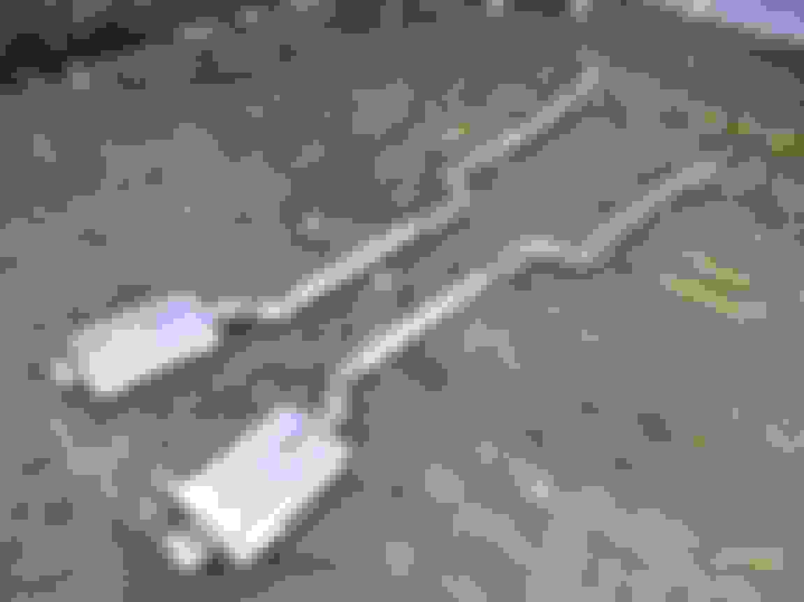
While I wait on the oil cooler, I decided to start mocking up what I think the tailpipes and tips could look like. I printed to-scale 3.5" exhaust tips, elongated slightly according to a 15* and 25* tip angle...
Here is the 3.5" 15* tip angle exhaust tip mocked up in place.. looks kinda small...
The location of good proportionality was about 1" inboard of the common plane shared between the bumper mount bolt head and the inboard edge of the tail light trim. With the exhaust lined up with those two it looked kinda strange having so many objects visually aligned to one reference line, so I moved the tip inboard until it looked decent in person, also taking into account the visual mass of the bumper between the tip and the outboard corner (right side) and the tip and the license plate recess (left side)...
With the 3.5" tip looking a bit anemic, I printed out a 4" tip (!!!) and in person it looks significantly more proportional, especially when you imagine a 1/4" air gap between the tip OD and the bumper notch...
The great work continues! I'm really digging all the oil lines and junction block. I've got to ask a few questions (1) how are you going to prime all that for first startup (2) will you have some kind of back-flow prevention to keep oil in all those lines between subsequent startups and (3) how much higher flow is your oil pump compared to stock?
4" tips will be just right. I like where you're mocking the placement. Are you just goofing around or are you thinking about doing the tips before first startup?
1) For first startup I'm going to disconnect the injector harness and coil pack harnesses and just keep cranking it over until I see oil pressure build up on my dash gauge. I'll prefill the oil filter and maybe the oil cooler as well, depending how enthusiastic I get
2) My back-flow prevention is just to work off pressure head and elevation.. the oil cooler will side load and I'll have the cooler lines go up and over the rad support (or thru it).. just making sure that the cooler is below the lines at some point, to prevent the claimed 0.8qt capacity of the cooler from gravity draining back into the pan after each shut down. I previously had similar-length cooler lines but to a bottom-feed oil cooler (system designed circa 2011.. I didn't know any better) and with cold starts after multiple days, the engine would fire upon 2nd crank or so (so no real cranking time to prime the oil system) and there was definitely a 1-2 second delay in the pressure building up on my dash gauge... gravity draining the oil cooler is bad!
3) I have a Melling high-volume pump, which I've logged in the past pushing up to ~80psi hot oil pressure at high rpm, so I know the physical pumping is good, I just need to keep the oil cool, and keep it in the cooler/lines when the engine is cold
I agree that the 4" tips look just right.. if I want to try this bumper notching exhaust arrangement I might as well go all the way right at the start with no compromise and use the arguably too-big tips just to get things cosmetically balanced.
I'm not expecting the oil cooler to arrive this week, and I really need the oil cooler in hand in order to finalize the angle of the intercooler in order to finish the intercooler top tank fabrication work. In the same parts order I also got the final 3.5" aluminum bend needed to finish the intercooler top tank. So short of adding some additional Holley sensor wiring, I'll have lots of time this weekend to start cutting and mocking up tailpipes from the axle to the bumper.......
Thanks for the explanation on the oil drain-back considerations. Since it's a closed system weird things can happen with siphoning so I though it was worth mentioning. I don't know if siphoning will happen in this system with the drain back lines from the turbos or other places - sometimes I just like to make things up in my head without thinking them all the way through, dump them onto a post, and let you sort out why my concerns are valid or ridiculous.
I didn't realize you were waiting on parts and just needed something fun to do w/ the tailpipes. Good luck notching out the bumper. Hope you can get away without re-chroming for now.
I'm going to run the Earl's Temp-A-Cure oil cooler, narrow 60-row version, flipped on its side. Much like the intercooler, this will let the oil flow vertically across many short paths, hopefully keeping the pressure drop to a minimum (stated 0.6psi/1.1psi drop for warm/cold oil). I haven't done much reading on the Earl's coolers other than they're literally the biggest ones I could find that would fit within the very (VERY) little room I have left. What also helped sell me was Holley stating that the fins have turbulators on them.. more surface area and turbulence is more efficiency.
I came about the Earl's unit in a roundabout way... I was originally looking at a same-size 60-row cooler from Setrab, but finding its part number online was very difficult. Then after looking on the Holley site, I noticed the "narrow 60 row" UltraPro cooler looked IDENTICAL.
As far as I can tell, size-for-size the UltraPro and Temp-A-Cure coolers are the same Setrab cores however the UltraPro has slightly larger fabricated end tanks (more oil capacity, and about 40% more $$) whereas the Temp-A-Cure has smaller end tanks. Also for the same narrow & 60 row size... the overall width (including mounting tabs) is stated as the same.. but the Temp-a-cure cooler has the fittings spaced a bit wider, so I'm not sure if that means the core is a bit wider or if the core is the same size but the fittings are just located differently between the two end tanks...
Equivalent Setrab narrow 60 row core stats...
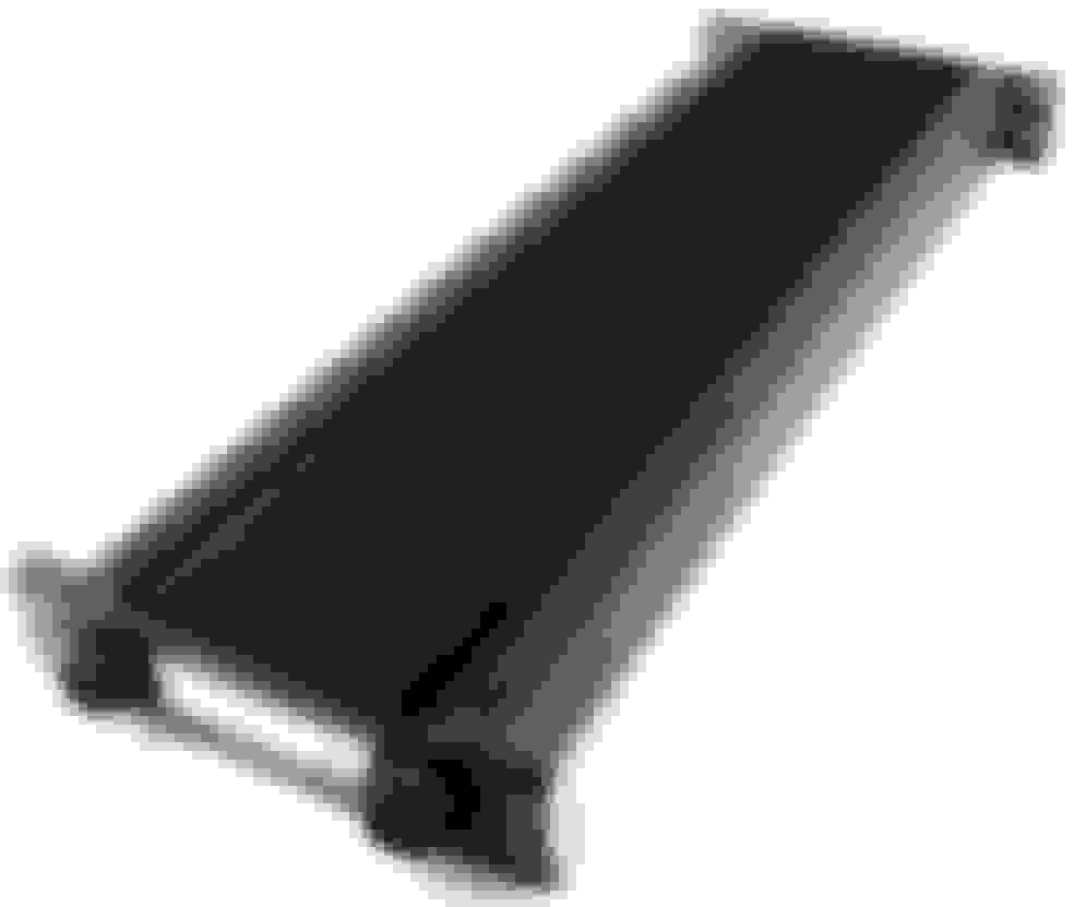
Setrab 60 row unit...
This is the UltraPro narrow 60 row cooler, stated 8.25" overall width (including mounting tabs), 4.8" fitting spacing, 0.8qt capacity, $499...
This is the Temp-A-Cure narrow 60 row cooler, stated 8.25" overall width (including mounting tabs), 5.125" fitting spacing, unknown capacity (would speculate 0.3-0.4qt), $349...
Good info. I'm glad to see Holley step up their game on the oilcoolers. (Ultrapro) I wonder if this is to aid the LT1 swap community that might be in the planning stages.
This weekend I got a fair amount done although it was varied across a bunch of different areas. A lot of my previous wiring was poorly crimped and/or just soldered and wrapped with electrical tape (my handiwork circa.... 2010-2011) so I wanted to inspect everything and anything that looked remotely suspect I re-terminal'd and crimped using my cheapo hydraulic hand crimper (for 4-8ga wiring) or my ratcheting crimper (10-16ga), with heat shrink over the terminals and new corrugated loom over top of that. I didn't take many pictures because most of it was late Saturday night, but the end result is pretty tidy so maybe next day time in the garage I'll snap a few pics. The work I completed Sat night and Sunday was:
- de-loomed the headlight/signals/horn/fans wiring and inspected/cleaned up while moving the wiring from under the driver's fender to under the passenger fender
- ran 4ga power wire from the firewall main power bulkhead terminal to the starter (crimped, heatshrink'd, loomed, then DEI heatshielded)
- ran 4ga power wire from alternator to starter (crimped, heatshrink'd, and loomed)
- ran 10ga power wire from the starter to rad support relays (crimped, heatshrink'd, loomed, then DEI heatshielded)
- started running wires from the added sensors to the firewall, to then pass thru and pin to Holley ECU
I also:
- welded in my custom rad support structure, primed it and painted
- got several potential rad hoses, started cutting and mocking up required aluminum bends to route upper/lower rad hoses
- installed front bumper brackets for good
- removed driver side downpipe to heat wrap around steering box, then re-install for good
- measured hood gaps and re-aligned, then adjusted hood locations
- filed bellhousing at starter nub to have a bit more clearance to passenger side downpipe v-band clamp
- cut passenger side fender inner lip to allow tire clearance at full bump (copied the trial cutting work I did on driver side fender months ago)
- removed gas tank to add a better vent system, as well as allow room and better safety for cutting rear bumper and bumper support structure for exhaust tips
Here's a good example why it's best to not solder a terminal or connection.. this was the starter solenoid that was just soldered and not crimped. This wire was ziptied to the starter to keep it out of the way.. and years of engine vibration was enough to make the copper strands start to break right at that harsh line of rigidity where the solder ended...
The other thing I wanted to hammer out is what a nice intercooler top tank would look like. Thought 3.5" tubing looks nice and smooth, so I wondered how I could use 3.5" bends, and this is what I came up with.
The mandrel bends on the core side are 45 degree bends that are rotated 36 degrees up from horizontal, and then the bends used for the merge are 60 degrees that are just oriented so that they're perpendicular to the core...
5 degree angle of the "shoulders"...
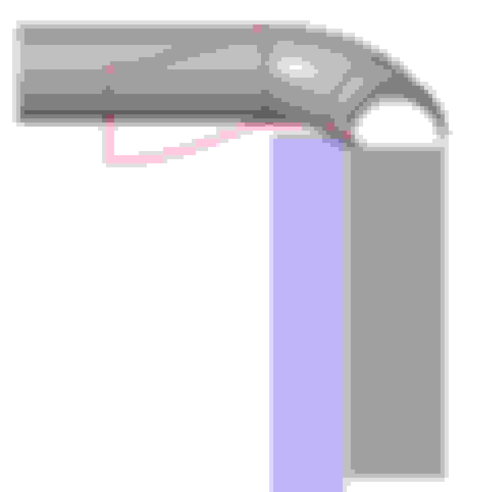
This is the necessary S-bend that I'll need to clear the rad but swoop back down to the throttlebody double-hump coupler. The red line also shows the bend I'll need to add to the filler plate to have the elbow clear the top-front edge of the radiator, but also smooth out the flow direction of the air leaving the top of the core...
Naturally I took a handful of 2D dimensions to measure and recreate the underside of the hood structure, which is shown... currently has 1/2" clearance.. if it ends up rubbing then the hammer will come out haha....
I started with the only bend I had left, a 90... which I cut into two 45's...
I then clamped it horizontally...
Which allowed me to scribe (with a steel block) and then marker the centerline of the bend plane
I then quickly milled a plate with the 36* angle on it, as a rotation guide, and clamped the tube once it was oriented in that 36* orientation...
Then used the steel block again to scribe the new centerline for the tube once rotated to that required angle. This scribe line will become the cut line...
Always easiest to go over that scribe line with a marker to make it extra clear once you start cutting... only want to cut once, the right way!...
I finished the cut line off around the bend by just eyeballing what my best guess would be for the contoured filler plate wrapping around the assembly...
And here we have the bisected tubes that will hopefully soon start taking shape on the top of the intercooler core....
Great update Joe. Nice to see some of the rewiring work. Crimp connectors are my preference now too. I don't think solder in of itself is the reason those strands were breaking. An F-crimp terminal which has both a wire AND a jacket/insulation crimp would likely have prevented the kind of failure you showed. A strand-only crimp terminal would likely do the same thing over time.
I'm really excited about the intercooler ductwork. It's going to be the perfect centerpiece for your engine bay. Thanks for sharing the progress!
Received the 120 degree 3.5" mandrel bend I was waiting on to make further progress on the intercooler top tank. From the 3D assembly I mocked up, it looked like I only needed 55* bends and not 60*, so cutting it was a bit more complicated than just hacking the bend into two pieces...
After one side was cut to 55*, then I trimmed the remaining 10* off the other side...
Used the same leaning-anglecut-piece method as before to orient the bend, to scribe the trim lines...
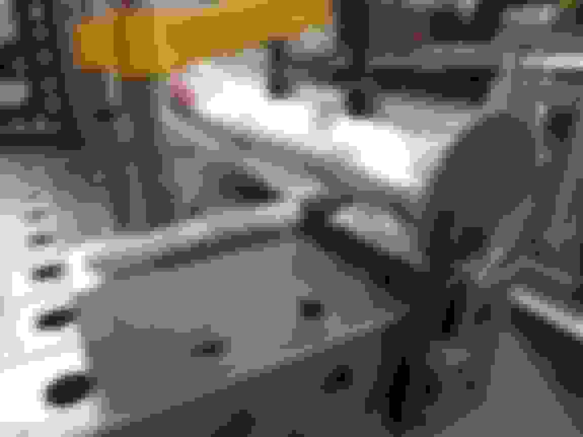
Skipping some of the boring stuff, I trimmed the sides and tack welded the two halves together...
And then joined the upper merge subassembly to the two core-side pieces. I aligned the bottom pieces to be perpindicular to the top piece, and made the top piece horizontal... clearly my eyeballed trim lines were a bit off, but all good.. still extra material to trim to final profile before I add the fill in plate pieces. I'm SUPER stoked on how flowy this end tank piece is looking....

 07-21-2018, 11:21 AM