
Hooker 1964-67 A-body LS swap system preview thread
 11-29-2017, 10:47 AM
#381
TECH Junkie
Thread Starter


Todd
We did rotate the engine mounts as mush as we could, so I do believe I will need to slot the hole in the frame.
The headers do look pretty darn parallel to the frame.
I'm using a digital app for the phone to measure. I don't have a balance on yet. I'll see about installing it.
Sounds like I'm close enough to get a drive shaft made, so I measure that and get one made.
You can take measurements off of the front of the crank snout if your balancer is not yet installed.
 11-29-2017, 07:46 PM
#382

It sounds like you are using the Clinometer app for your phone, which is what I use and is good and accurate if your phone model has nice flat sides on it (I use an old iphone 5).
You can take measurements off of the front of the crank snout if your balancer is not yet installed.
You can take measurements off of the front of the crank snout if your balancer is not yet installed.
I did measure off the crank snout and any other surface I could find. It's consistently 4.2-4.3 deg. It seams like the amount it has to move up to gain even 1 deg is unrealistic.
I'm going to work on getting a drive shaft, that could be a week or two away.
The T56 Magnum is supposed to be on the lower mount of the cross member, correct?
11-29-2017, 08:44 PM
#383
TECH Junkie
Thread Starter
Todd, Yes to the clinometer app.
I did measure off the crank snout and any other surface I could find. It's consistently 4.2-4.3 deg. It seams like the amount it has to move up to gain even 1 deg is unrealistic.
I'm going to work on getting a drive shaft, that could be a week or two away.
The T56 Magnum is supposed to be on the lower mount of the cross member, correct?
Last edited by Toddoky; 11-29-2017 at 08:59 PM.
11-29-2017, 09:33 PM
#384
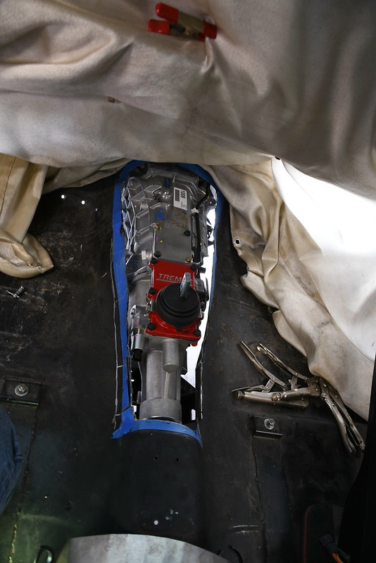
Don't get too caught up in any one particular measurement at the moment, get your driveshaft in and let me know when you get to that point. Did you do a T-cut in the floor over your transmission? What specific model/year A-body is your car? What rearend are you using? Post up a side view shot of your car that shows it's ride height/stance if you can so I can see what you're working with overall.

Tin Man fab

 11-29-2017, 10:50 PM
#386
TECH Senior Member

NICE ride, Troy!

 11-30-2017, 12:16 AM
#389
TECH Senior Member
 12-15-2017, 05:28 PM
#390
Todd, so I received my drive shaft from Strange Engineering.
the measurements are Engine/trans are @ 5 deg down the drive shaft is @ 1 deg and the diff is @ 3 deg up.
I do have adj upper rear control arms.
I'm still perplexed as to why the eng/trans are @ 5 deg. The trans is on the lower of the two pads on the cross member. Also, I mounted the cross member as per the directions. It is one hole shy of being all the way back. At this placement the bolts for the trans mount will not start in the mount. They are hitting on the front edge of the slot in the cross member. It would probably work if I move the cross member forward one hole, (now two from the back).
I'm using factory GM 2000 f body engine mounts.
12-15-2017, 06:00 PM
#391
TECH Junkie
Thread Starter
Todd, so I received my drive shaft from Strange Engineering.
the measurements are Engine/trans are @ 5 deg down the drive shaft is @ 1 deg and the diff is @ 3 deg up.
I do have adj upper rear control arms.
I'm still perplexed as to why the eng/trans are @ 5 deg. The trans is on the lower of the two pads on the cross member. Also, I mounted the cross member as per the directions. It is one hole shy of being all the way back. At this placement the bolts for the trans mount will not start in the mount. They are hitting on the front edge of the slot in the cross member. It would probably work if I move the cross member forward one hole, (now two from the back).
I'm using factory GM 2000 f body engine mounts.
the measurements are Engine/trans are @ 5 deg down the drive shaft is @ 1 deg and the diff is @ 3 deg up.
I do have adj upper rear control arms.
I'm still perplexed as to why the eng/trans are @ 5 deg. The trans is on the lower of the two pads on the cross member. Also, I mounted the cross member as per the directions. It is one hole shy of being all the way back. At this placement the bolts for the trans mount will not start in the mount. They are hitting on the front edge of the slot in the cross member. It would probably work if I move the cross member forward one hole, (now two from the back).
I'm using factory GM 2000 f body engine mounts.
12-15-2017, 06:30 PM
#393
TECH Junkie
Thread Starter
12-15-2017, 06:56 PM
#394
I have some photos of the top of the frame rails when I was replacing the trunk floor. Maybe I'll get lucky and be able to see the vin in one of the photos.
12-15-2017, 07:45 PM
#395
TECH Junkie
Thread Starter
See what you can find, any variable you can validate helps to narrow things down. Are the crossmember frame adapters raised up all the way against the bottom of the top frame flanges?

 12-26-2017, 04:14 PM
#397
So, I'm still trying to get this ironed out.
With the trans sitting on the two shims provided ( 1/2" ) it is 4.8* down And I match the pinion at 4.8* down And the shaft is at .8* down.
this gives me operating angles of 3.9* on each u joint. This seams unacceptable.
If I move the trans up and add another 1/2' spacer for a total of 1" tall spacer.
I get 4* down on the trans and the pinion is at 4*down and the shaft is at 2*
This gives me 2* operating angle on both u joints. This seams perfect. Although it would require some modification of the floor brace at minimum, probably some extra tunnel mods as well.
When I saying down on the pinon I'm say the angle of the pinion shaft from front to back just like the trans and shaft are down from front to back.
http://spicerparts.com/calculators/d...gle-calculator
12-26-2017, 06:15 PM
#398
TECH Junkie
Thread Starter
You are closing in on your final set-up geometry. Operating angles of 3.9 degrees are definitely excessive...if you can obtain 2 degree operating angles on both U-joints and have clearance between your oil pan and tie rod ends up front then you are in a good place at that position. Take the car out for a test drive set where you have it (2 degree operating angles) and if you get vibration under acceleration you'll need to tip your pinion down towards the ground a degree or two as a final adjustment...if you go too far it will introduce vibration under deceleration.
With your indication that your floor brace might need clearancing, it's possible your floor has sagged over the years somewhat, which does come up from time to time.
With your indication that your floor brace might need clearancing, it's possible your floor has sagged over the years somewhat, which does come up from time to time.
Last edited by Toddoky; 12-26-2017 at 06:23 PM.
02-09-2018, 11:47 AM
#399

Toddoky I was wondering if you could help I think I was sent 2 left side pipes on my 70501311RHKR. The left hand side goes under crossmember and the right is up into cross member so both pipes have the same bends in them. I've emailed pictures to holley a couple times phoned a few times for the last month and the only thing I've been told is engineering is looking at it. I would like to get it resolved as I waited for 3 months after ordering to receive exhaust now a month with no one getting back to me as I am waiting to put my body back on the frame.