
LS1 Swap FAQs
 12-14-2009, 05:41 PM
#161
Teching In

Join Date: Jun 2009
Posts: 2
Likes: 0
Received 0 Likes
on
0 Posts
Hi there,
have searched this thread for pin outs on a 2003 GTO LS1 with T56 and manual throttle body. but none found so far..
If anyone can help please let me know.
Thanks for all the great info posted by all.
Coop
have searched this thread for pin outs on a 2003 GTO LS1 with T56 and manual throttle body. but none found so far..
If anyone can help please let me know.
Thanks for all the great info posted by all.
Coop
 02-27-2010, 10:04 AM
#162
Launching!
iTrader: (16)
Join Date: Jun 2007
Location: pierre SD
Posts: 255
Likes: 0
Received 0 Likes
on
0 Posts
just found this. for newer silverados. good description of of underhood fuse block and connectors. maybe the mods can move it towards the front of the thread
http://images.google.com/imgres?imgu...26tbs%3Disch:1
http://images.google.com/imgres?imgu...26tbs%3Disch:1
 05-16-2010, 12:38 AM
#164
Teching In

Join Date: May 2010
Location: Perth, Western Australia
Posts: 25
Likes: 0
Received 0 Likes
on
0 Posts
did numerous searches but cant find answers to these tough questions:
base info: '04 Holden LS1 swapped into a Jeep Wrangler using the LS1 computer exclusively but no PIM or BCM (deleted those from the wiring as i have aftermarket gauges and thought there was no use for them). i've yet to wire in the MIL but did wire in the DLC. ive been able to connect my laptop software via the DLC and observe engine functions without issue but cannot pull codes (even when i deliberately unplug things like injectors, sensors, etc...)
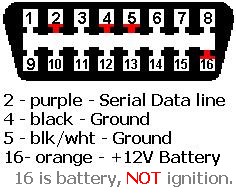
my questions are: is the reason i cant pull codes because i need the PIM (&/or the BCM) to convert the class 2 serial data signal from the PCM to a UART serial data signal at the DLC (would be pin 9 on the DLC and pin 6 for "diag enable" from the PIM)? why am i able to connect my laptop to the DLC and watch engine management or is that separate info from DTC signals (looks like the same wire providing both information from the PCM)? and does it have anything to do with the fact the MIL circuit itself is not present? do i need the PIM (&/or BCM) to run the MIL or can i simply run 12V to a bulb and ground it thru the PCM's serial data output? im worried there are differences in circuit voltages if i do this and dont want to fry the PCM. at present, the DLC is wired as follows: pin 2 is the PCM class 2 serial data output signal. pins 4 & 5 are grounds and are wired together (is this okay? ive seen differing opinions). pin 16 is direct 12 volt battery power. any help is appreciated. would like to pull codes (im sure there are many) before we go to the dyno shop for software editing. i seriously doubt i simply have no codes stored but spoze its a possibility (like winning Lotto). LOL. thanks in advance.
base info: '04 Holden LS1 swapped into a Jeep Wrangler using the LS1 computer exclusively but no PIM or BCM (deleted those from the wiring as i have aftermarket gauges and thought there was no use for them). i've yet to wire in the MIL but did wire in the DLC. ive been able to connect my laptop software via the DLC and observe engine functions without issue but cannot pull codes (even when i deliberately unplug things like injectors, sensors, etc...)
my questions are: is the reason i cant pull codes because i need the PIM (&/or the BCM) to convert the class 2 serial data signal from the PCM to a UART serial data signal at the DLC (would be pin 9 on the DLC and pin 6 for "diag enable" from the PIM)? why am i able to connect my laptop to the DLC and watch engine management or is that separate info from DTC signals (looks like the same wire providing both information from the PCM)? and does it have anything to do with the fact the MIL circuit itself is not present? do i need the PIM (&/or BCM) to run the MIL or can i simply run 12V to a bulb and ground it thru the PCM's serial data output? im worried there are differences in circuit voltages if i do this and dont want to fry the PCM. at present, the DLC is wired as follows: pin 2 is the PCM class 2 serial data output signal. pins 4 & 5 are grounds and are wired together (is this okay? ive seen differing opinions). pin 16 is direct 12 volt battery power. any help is appreciated. would like to pull codes (im sure there are many) before we go to the dyno shop for software editing. i seriously doubt i simply have no codes stored but spoze its a possibility (like winning Lotto). LOL. thanks in advance.
Last edited by rodgebone; 05-16-2010 at 07:30 PM.
06-02-2010, 12:16 PM
#167
Teching In

Join Date: Jun 2010
Posts: 2
Likes: 0
Received 0 Likes
on
0 Posts
Okay, yes I'm new but have been reading for days. Got the hang of this, ready to start clipping wires but have 1 or 2 questions before I screw up a good donor harness.
Taking 6.0L & 4L80e out of 2001 GMC Sierra 2WD w/ harness, putting in old car, 72 grand prix.
Question, I cannot find a specific pin out diagram for the 2001 6.0L. I realize newer one are different, 03+ due to drive by throttle and so on. Will any of the older 99-02 pinouts work for me or does someone have specifically what I need? Does it matter on 5.3L vs 6.0L or is it really the exact same operations & pin removals? Are there subtle differences in the difference years or LS motors as far as wiring mods?
Muchos Gracias!
nick
 06-11-2010, 04:50 PM
#170
On The Tree
Join Date: Apr 2010
Location: 78155 TX
Posts: 116
Likes: 0
Received 0 Likes
on
0 Posts
[QUOTE=
hey here are the wires you need
99 LS1 PCM to Front Harness
Large Plug C100 Plug
A PNK Hot in Run and Start (IGN/INJ Bank 1 15A)
B DK GRN/WHT PCM 43 A/C Clutch Relay Control
C DK GRN PCM 18 A/C Clutch Status
D GRY TPS +5v to TCS
E DK BLU TPS signal to TCS
G PNK Hot with IGN 1 Relay Engaged (Tranny/EGR 15A)
H DK BLU PCM 33 Cooling Fan 2 and 3 Relay Control
J DK GRN PCM 42 Cooling Fan 1 Relay Control
K BLK TPS sensor low to TCS
C101 Plug
A YEL/BLK Low Coolant Sensor
B PNK Hot in Run and Start (IGN/INJ Bank 2 15A)
C BRN PCM 36 Air Pump Relay Control
D DK GRN/WHT PCM 9 Fuel Pump Relay Control
E PNK/BLK PCM 19 Ignition Positive Voltage for PCM
G ORN PCM 57 Battery Positive Voltage for PCM
H BLK/WHT Ground
K GRY/BLK PCM 53 TCS Spark Retard Signal to Brake Control Module
C105 Plug
B PNK Hot with IGN 1 Relay Engaged (TCC Stop Lamp Switch/MAF/O2 20A)
D DK GRN PCM 37 Cruise Control Inhibit
F WHT PCM 13 Cruise Engaged Signal
G WHT PCM 10 Tach out to Brake Control Module
H PPL PCM 4 AIR Solenoid Relay Control
These are all of the pins/wires I did not use:
220- E,H,J,K
230- A,C,F,G,H,J
C100- B,C,D,E,K
C101- A,C,K
C105- D,F,H
All the pink wires run into one wire which is ignition switch on i ran it to my ecm ignition on fuse on my truck fuse box. and the orange wire i ran a hot wire to it from my battery.[/QUOTE]
so according to this i need ignition power to c100 A,G C101 B,E C105 B?
and constant power to C101 G?
06-15-2010, 03:17 PM
#171

okay, yes i'm new but have been reading for days. Got the hang of this, ready to start clipping wires but have 1 or 2 questions before i screw up a good donor harness.
Taking 6.0l & 4l80e out of 2001 gmc sierra 2wd w/ harness, putting in old car, 72 grand prix.
Question, i cannot find a specific pin out diagram for the 2001 6.0l. I realize newer one are different, 03+ due to drive by throttle and so on. Will any of the older 99-02 pinouts work for me or does someone have specifically what i need? Does it matter on 5.3l vs 6.0l or is it really the exact same operations & pin removals? Are there subtle differences in the difference years or ls motors as far as wiring mods?
Muchos gracias!
Nick
2001 GMC Sierra 6.0 Vin U P2.pdf
2001 GMC Sierra 6.0 Vin U P3.pdf
2001 GMC Sierra 6.0 Vin U P4.pdf
2001 GMC Sierra 6.0 Vin U P5.pdf
06-16-2010, 10:48 PM
#173
On The Tree
Join Date: Apr 2010
Location: 78155 TX
Posts: 116
Likes: 0
Received 0 Likes
on
0 Posts
Okay, checked out my wiring harness conversion and found quite a few wires removed.
2001 LS1 5.7L with 4L60E A4 Transmission
Blue connector....
23 - Low Reference
25 - HO2S Low Signal Bank 2 Sensor 2
28 - HO2S Low Signal Bank 1 Sensor 2
32 - CPP Switch Signal ? what is CPP?
65 - HO2S High Signal Bank 2 Sensor 2
68 - HO2S High Signal Bank 1 Sensor 2
70 - Oil Level Switch Signal
Red Connector....
4 - Air Injection Reaction Solenoid Relay - Coil - Control
13 - Cruise Control Engage Signal
34 - Evaporative Canister Purge Solenoid Control
36 - AIR Pump Relay Control
37 - Cruise Control Inhibit Signal
45 - Evaporative Canister Vent Solenoid Control
46 - MIL Control ? what does MIL stand for?
53 - Ignition Retard Signal
54 - Fuel Level Sensor Signal
64- Fuel Tank Pressure Sensor Signal
2001 LS1 5.7L 4L60E four speed automatic
Removed pins and wires from Blue PCM connector....
23, 25, 28, 32, 65, 68 and 70
Removed pins and wires from Red PCM connector....
4, 7, 13, 34, 36, 37, 45, 53, 54 and 64
Bundle these wires together and route into the cab of vehicle.....
Blue 33 - Purple - TCC Brake Switch Signal - to brake switch - normal 12v positive and Zero
Volts when brake pedal is depressed .
Blue 34 - Orange/Black - Neutral Safety Switch
Blue 46 - Brown/White - Malfunction Indicator Light
Red 17 - Green/White - A/C request switch
Red 30 - Dk Blue - Fuel Enable Control - to VATS if not disabled in the PCM
Red 42 - Tan or Tan/Black - TCC Solenoid Valve Control
Red 50 - Green/White - Vehicle Speed Sensor Signal
Six fuse power block....
12V - Red - always "ON" from battery to three fused outlets
1. 30 amp 12V from fuse to terminal 87 for low fan relay
2. 30 amp 12V from fuse to terminal 87 for high fan relay
3. 10 amp 12V from fuse to PCM Blue 20 and 57
12V - Pink - from ignition "ON" switch to three fused outlets
1. 20 amp 12V from fuse to A/C relay terminal 87
2. 15 amp 12V from fuse to PCM Connector Blue 19
3. 15 amp 12V from fuse to Fuel Pump Relay terminal 87
Bosch Type Relay 1.
Low Speed Fan Relay
Terminal 85 connect to PCM Blue 42 - Dark Green
Terminal 30 Connect to Fan positive
Terminal 86 Connect to constant 12V Power Supply
Terminal 87 Connect to Switched 12V Power Supply
Bosch type Relay 2.
High Speed Fan Relay
Terminal 85 connect to PCM Red 33 - Dark Blue
Terminal 30 Connect to Fan positive
Terminal 86 Connect to constant 12V Power Supply
Terminal 87 Connect to Switched 12V Power Supply
Bosch type Relay 3.
Fuel relay
Terminal 85 connect to PCM Red 9 - Dark Green/White
Terminal 30 Connect to fuel pump 12V input
Terminal 86 Connect to Ground - black/white
Terminal 87 Connect to Switched 12V Power Supply
Bosch type Relay 4.
A/C relay
Terminal 85 connect to PCM Red 43 - Green/White - A/C Clutch Relay Control
Terminal 30 Connect to PCM Red 18 - Dark Green - A/C Compressor Clutch Supply Voltage
Terminal 87 Connect to switched 12V Power Supply
Terminal 86 Connect to PCM Blue 19 - Pink - Ignition 1 Voltage
My only concern is Relay 4. I don't see the logic there. It seems to me that Terminal 86 - Blue 19 - should have 12 Volts at the switch unless it is 12 Volts output from the PCM instead of input into the PCM. GM has always used the pink wire as switched power, red as constant 12V and Purple as the main starter solenoid lead.
Posted by
Magnus
Re: wiring questions
________________________________________
Hmm.. ok Lets go over the list..
Oil Pressure: Optional but recommended
Clutch Anticipate Switch Signal: uncertain
IGN Power for TCC Stop Lamp Switch: Optional but recommended
TCC/Cruse Brake Switch: Optional but recommended (Paired with above)
Ground
PNP Switch Signal: Optional
Low Coolant Indicator: Optional
VSS Output: Optional but recommended
5V Feed (Fuel tank pressure): Optional
MIL Control: Optional but recommended
EVAP Canister Vent Valve Control: Optional
Theft Deterrent Fuel Enable: Required
A/C Request: Optional
Fuel Ground: Optional depending on how your fueling is setup
Fuel Tank Pressure: Optional
Fuel Level Input: Optional
Serial Data (Class 2): Optional but recommended
Hot in Run and Start (IGN/INJ Bank 1 15A): Required
A/C Clutch Relay Control: Optional
A/C Clutch Status: Optional
TPS +5v to TCS: Optional
TPS signal to TCS: Optional
with IGN 1 Relay Engaged (Tranny/EGR 15A): Required
Cooling Fan 2 and 3 Relay Control: Optional but HIGHLY recommended
Cooling Fan 1 Relay Control: Optional but HIGHLY recommended
TPS sensor low to TCS: Optional
Low Coolant Sensor: Optional
Hot in Run and Start (IGN/INJ Bank 2 15A): Required
Air Pump Relay Control: Optional
Fuel Pump Relay Control: Required most likely
Ignition Positive Voltage for PCM: Required
Battery Positive Voltage for PCM: Required
Ground:
TCS Spark Retard Signal to Brake Control Module: Optional
Hot with IGN 1 Relay Engaged (TCC Stop Lamp Switch/MAF/O2 20A): Required
Cruise Control Inhibit: Optional
Cruise Engaged Signal: Optional
Tach out to Brake Control Module: Optional (Re-use for dash tach)
AIR Solenoid Relay Control: Optional
Posted By
MrDude_1
let me take a min to explain what that means (i know i wish someone did that for me first.. lol)
when you get a pullout that has the harness on the car, everything is connected except:
3 connectors that were underhood. (named C100,C101,C105)
2 connectors that used to connect under the dash (220,230)
so these 5 connectors are teh ONLY wires we're worred about.
in a nutshell... give ignition power to the pink wires, constant power to the orange ones, take off VATS, and it runs.
the other wires you hook up are just gauge wires, reverse lights, ect.... nothing hard.
its ALMOST a stand alone harness already... only diff is it will have a couple extra wires left after its hooked up.. not a big deal..
theres one more wire not listed there.. its a thick purple wire that goes to the starter.
when it gets +12v, the starter turns the motor over.
also, i bought HPtuners... you will either need HPtuners/EFILive/etc., or have your PCM flashed by someone to remove the trouble codes and VATS.... i could give you a step by step on doing it easily.... but HPtuners/EFILive is a little pricy. a tune is a cheaper route, but HPtuners/EFILive give you the scanner thats very useful.. along with the ability to change stuff at will... your call on that.
Quote:
Originally Posted by SatisTraction
did any of you leave the diagnostic plug connected so that you could connect a tuner for the computer?
yup.
all i did was go into the junkyard and grab one off of a GM ODBII car.....
posted by flippincamaro
hey here are the wires you need
99 LS1 PCM to Front Harness
Large Plug C100 Plug
A PNK Hot in Run and Start (IGN/INJ Bank 1 15A)
B DK GRN/WHT PCM 43 A/C Clutch Relay Control
C DK GRN PCM 18 A/C Clutch Status
D GRY TPS +5v to TCS
E DK BLU TPS signal to TCS
G PNK Hot with IGN 1 Relay Engaged (Tranny/EGR 15A)
H DK BLU PCM 33 Cooling Fan 2 and 3 Relay Control
J DK GRN PCM 42 Cooling Fan 1 Relay Control
K BLK TPS sensor low to TCS
C101 Plug
A YEL/BLK Low Coolant Sensor
B PNK Hot in Run and Start (IGN/INJ Bank 2 15A)
C BRN PCM 36 Air Pump Relay Control
D DK GRN/WHT PCM 9 Fuel Pump Relay Control
E PNK/BLK PCM 19 Ignition Positive Voltage for PCM
G ORN PCM 57 Battery Positive Voltage for PCM
H BLK/WHT Ground
K GRY/BLK PCM 53 TCS Spark Retard Signal to Brake Control Module
C105 Plug
B PNK Hot with IGN 1 Relay Engaged (TCC Stop Lamp Switch/MAF/O2 20A)
D DK GRN PCM 37 Cruise Control Inhibit
F WHT PCM 13 Cruise Engaged Signal
G WHT PCM 10 Tach out to Brake Control Module
H PPL PCM 4 AIR Solenoid Relay Control
These are all of the pins/wires I did not use:
220- E,H,J,K
230- A,C,F,G,H,J
C100- B,C,D,E,K
C101- A,C,K
C105- D,F,H
All the pink wires run into one wire which is ignition switch on i ran it to my ecm ignition on fuse on my truck fuse box. and the orange wire i ran a hot wire to it from my battery.
and constant power to C101 G?
07-14-2010, 06:20 PM
#174
Teching In

Join Date: Jul 2010
Posts: 3
Likes: 0
Received 0 Likes
on
0 Posts
wonder if anyone can shed anylight on installing a ls7 into a kitcar i have looked at the wiring configs and can anyone help please basics to get engine started i have pedal *** ,full engine harness and all o2 sensors etc
thanks any input would be graetly appreciated
pete
thanks any input would be graetly appreciated
pete
 03-01-2011, 03:25 PM
#178

Glad I came across this thread, thanks! I am having some mixed emotions and info on swapping a 98 Ls1 (Camaro) on a first gen, so will dig through here deeper for more info. Thanks!
04-24-2011, 07:21 AM
#179
I found a very useful adapter kit with 5 different fittings that will connect a 1/8 x27 NPT sender to M10 x 1, M12 x 1.5, M14 x 1.5 and M16 x 1.5 and 1/8" x 28 BSP. This will enable you to put a temp sender in the passenger side head without drilling or tapping. Also some aftermarket gauge manufacturers are stocking 12 mm senders now. Check with your gauge company.
It is made by EQUUS, part number is #6848. Cost was less than $8 plus tax. I got it from my local Auto Parts. Much less expensive than the $16.50 for one fitting from one of the conversion specialists.
Pat
It is made by EQUUS, part number is #6848. Cost was less than $8 plus tax. I got it from my local Auto Parts. Much less expensive than the $16.50 for one fitting from one of the conversion specialists.
Pat
Tom
